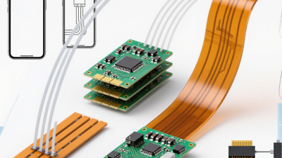
How to Choose a Flexible Printed Circuit Board?
Choosing a flexible printed circuit board starts with its job, not a catalog. A hinge in a handheld device may bend thousands of times. A short flex link inside a camera may move only during assembly. Those applications need different materials, copper, and stackups. Small details matter.
Flexible-circuit specialist Joe Fjelstad has written extensively about flexible-circuit design. In paraphrase, his guidance becomes: “Design for the real bend, not the ideal drawing.” That distinction is practical. A tight bend near a connector can stress copper traces, even when the board fits the enclosure perfectly. Check whether the circuit will flex continuously or remain mostly static. Then review bend radius, layer count, copper type, coverlay, and adhesive with a qualified fabricator.
Look at the whole assembly. A warm, humid enclosure may call for different material choices than a dry, room-temperature device. Connector placement matters, too. So do assembly tolerances. A prototype can reveal what a clean CAD view cannot: a stiff transition, a crease, or a cable that presses against a sharp edge. It is easy to overlook these details. Teams do.
There is no universal best option. Compare supplier capabilities, request stackup guidance, and verify design rules against the current project requirements. If the flex will move repeatedly, ask how the proposed construction supports that motion. A lower initial price may not reflect performance over the product’s life. The choice deserves a second look.
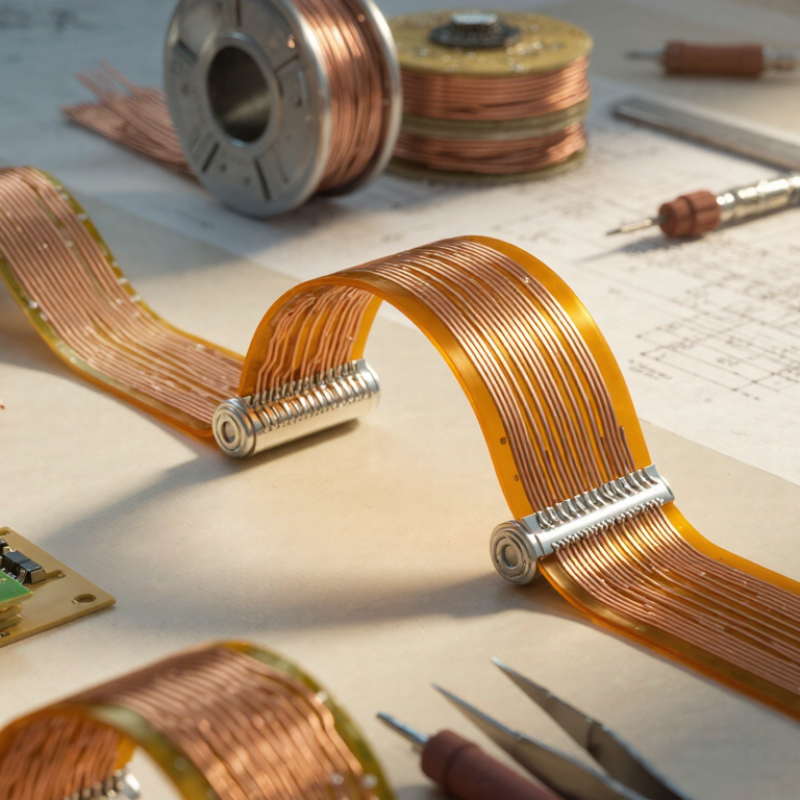
Define the Application and Electrical Requirements
Choosing a flexible printed circuit board starts with its real job, not its shape. Record operating voltage, peak current, signal speed, and required impedance. A sensor lead inside a sealed device has different needs from a moving hinge cable. Note the ambient temperature, moisture, vibration, and available space. Grand View Research valued the global flexible printed circuit board market at USD 20.4 billion in 2023. Its market analysis projected 10.4% annual growth from 2024 to 2030. That expansion makes careful requirement-setting more important, not less.
Translate those needs into a usable design brief. State whether bends are static or repeated, and specify bend location and cycle life. Include trace length, connector type, shielding needs, and any controlled-impedance targets. IPC-2223 provides design guidance for flexible printed boards, including construction and bend considerations. For current-carrying traces, confirm copper thickness and temperature rise with a qualified designer or fabricator. This is easy to miss. A cable that passes a bench test may fail after repeated movement or heating. Keep tolerances realistic, too; a very tight bend radius can undermine an otherwise sound layout. Define how the board will be tested before approving the design.
Set Bend, Thickness, and Routing Constraints
A flexible PCB needs clear bend, thickness, and routing limits before layout begins.
Define whether the board bends once during installation or moves repeatedly in service. Static and dynamic bends place different demands on copper and materials. There is no universal bend-radius value. Use the fabricator’s guidance for the chosen stack-up.
Small details matter.
Set the permitted bend radius alongside the total flex thickness. Copper type, coverlay, and adhesive layers all affect how the board behaves. A thicker stack may need a wider curve than expected. Keep vias, components, and abrupt width changes outside the bend zone. Route traces across the bend, rather than along its axis, where the design allows. Smooth curves reduce stress concentrations. A tidy CAD route can still hide a weak spot.
Mark bend zones and routing restrictions clearly in the drawing, including the intended bend direction and minimum radius. Ask the fabricator to review the stack-up before routing is frozen. Then test a sample using the real enclosure or motion path. A bench test may miss a tight corner inside the product.
I would revisit the layout if the sample creases, shifts, or shows copper damage; early assumptions are not always right.
Compare Fabrication Processes and Design Capabilities
How to Choose a Flexible Printed Circuit Board?
Compare fabrication processes before comparing quotes. Most flexible circuits use subtractive etching: copper is laminated to polyimide, then unwanted copper is removed. It suits many designs and supports fine traces, but etching can narrow small features. Additive or semi-additive processes build copper selectively, which may help with dense routing, though capability depends on the fabricator. Ask for minimum trace width, spacing, copper thickness, and layer count—not just a general claim of “high density.”
Design choices matter just as much. A single-layer circuit bends easily and keeps costs down; multilayer circuits route more signals but add thickness and stiffness. Rolled-annealed copper often suits repeated bending, while electrodeposited copper may fit less demanding flex areas. Specify whether a section moves repeatedly or bends only during assembly. One easy-to-miss detail: a sharp bend near a plated via can invite cracking. Set bend zones, radii, and stiffener locations early. Then review a fabrication drawing with the supplier. A tiny connector pad may look fine on screen, yet become difficult to assemble.
I might still underestimate that trade-off; prototypes often reveal what the drawing missed.
Verify Quality, Reliability, and Supplier Fit
Choosing a flexible printed circuit board starts with checking how it will be used. Note the bend direction, expected movement, temperature range, and space available for connectors. A drawing may look clear, yet a tight fold near a solder joint can create stress during assembly. Small details matter.
Review the supplier’s quality controls, not just a sample board. Ask how material thickness, copper weight, trace spacing, and coverlay alignment are inspected. Request test records for continuity and insulation resistance, plus clear acceptance criteria. For moving applications, ask how flex-life testing matches your actual bend radius and cycle count. A test is only useful when it resembles real use. That distinction is easy to miss.
Reliability also depends on communication and process stability. Check whether the supplier can explain design limits, flag unsupported tolerances, and document changes between prototype and production. Compare lead times, engineering support, and capacity against your schedule. During a design review, even a minor connector-position change can affect tooling or assembly access. I would still leave room for revision; early estimates are not always precise. Share drawings, expected volumes, and inspection needs before requesting a quote, then see whether the response addresses those specifics.