Icon about-block-ico-1 Icon about-block-ico-2 Icon about-block-ico-3 Icon about-block-ico-4 Icon announcement-close Icon arrow-left Icon arrow-right Icon arrow-sm Icon asterisk Icon banner-transparent-vector Icon btn-callback-ico Icon careers-item-location Icon careers-item-time Icon careers-item-type Icon careers-mail-ico Icon careers-phone-ico Icon careers-search-ico Icon careers-single-hero-vector Icon careers-single-more-vector Icon careers-vector Icon check Icon close Icon dfm-image-left-vector Icon dfm-image-right-vector Icon document Icon download-popup-vector Icon dropdown Icon envelope Icon facebook Icon faq-banner-bg Icon faq-title-ico-active Icon faq-title-ico Icon featured-links-block-bg Icon figure-1 Icon figure-10 Icon figure-11 Icon figure-12 Icon figure-13 Icon figure-14 Icon figure-15 Icon figure-2 Icon figure-3 Icon figure-4 Icon figure-5 Icon figure-6 Icon figure-7 Icon figure-8 Icon figure-9 Icon file-upload Icon form-sidebar-back Icon form-step-done Icon gmap-marker-group-icon Icon gmap-marker-icon Icon header-profile-ico Icon instagram Icon link Icon linkedin Icon loader Icon mail Icon phone Icon play-yt Icon play Icon post-nav-arr-left Icon quote-banner-vector Icon quote-block-aside-vector Icon quote-contact-phone-ico Icon quote-contact-position-ico Icon sidebar-location Icon sidebar-phone Icon technology-banner-nav-left-vector Icon technology-banner-nav-right-vector Icon twitter Icon webinar-item-date-vector Icon whitepaper-img-ico-left Icon whitepaper-img-ico-right Icon whitepapers-listing-banner-ico Icon whitepapers-single-aside-vector Icon youtube Icon yt-play-button

What Is the Best Type of Flex Circuit Board in 2026?

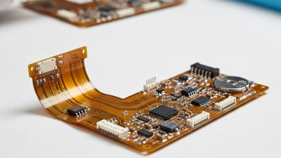
Choosing the best flex circuit board in 2026 is not a contest between the most layers and the newest materials. It is a fit question. A single-sided circuit may suit a simple sensor link, while a multilayer design can route dense signals through a compact camera module. Rigid-flex can combine bendable sections with stable component-mounting areas. Each choice changes cost, assembly, and reliability. Small details matter: a connector near a fold, a tight bend around a metal frame, or repeated movement inside a wearable device. Easy to miss.

MarketsandMarkets’ Flexible Printed Circuit Board Market report forecasts growth from USD 26.3 billion in 2024 to USD 40.3 billion by 2029. That outlook reflects expanding uses across consumer electronics, automotive systems, medical devices, and other sectors. It does not mean every product needs a complex board. IPC-2223C, the industry’s sectional design standard for flexible and rigid-flex printed boards, offers guidance for matching construction to mechanical and electrical requirements. This guide compares common flex circuit board types through those practical trade-offs, including layer count, bend behavior, space, and manufacturing needs. The right answer depends on the job. And sometimes the brief is incomplete. A promising design on paper may still need prototype testing, because material choice, copper construction, and assembly conditions can change performance. We’ll weigh the evidence, flag the compromises, and explain what to check before settling on a design.
What Is the Best Type of Flex Circuit Board in 2026?

Flex Circuit Types: Single-Sided, Double-Sided, and Multilayer

In 2026, the best flex circuit type depends on the signals, space, and movement your product requires. A single-sided circuit places copper on one side of the flexible base film. It suits straightforward connections in compact devices, such as a small sensor with components mounted along one surface. Its simpler stack can reduce thickness and make bending easier to manage. That simplicity matters.

A double-sided circuit has copper layers on both sides, connected through plated holes. It can carry more connections in a similar footprint, but its added structure calls for careful routing and bend-zone planning. Keep vias and components away from areas that flex repeatedly. A sharp crease near a via can become a weak point. I have seen early layouts look tidy on screen, then need changes after bend testing.

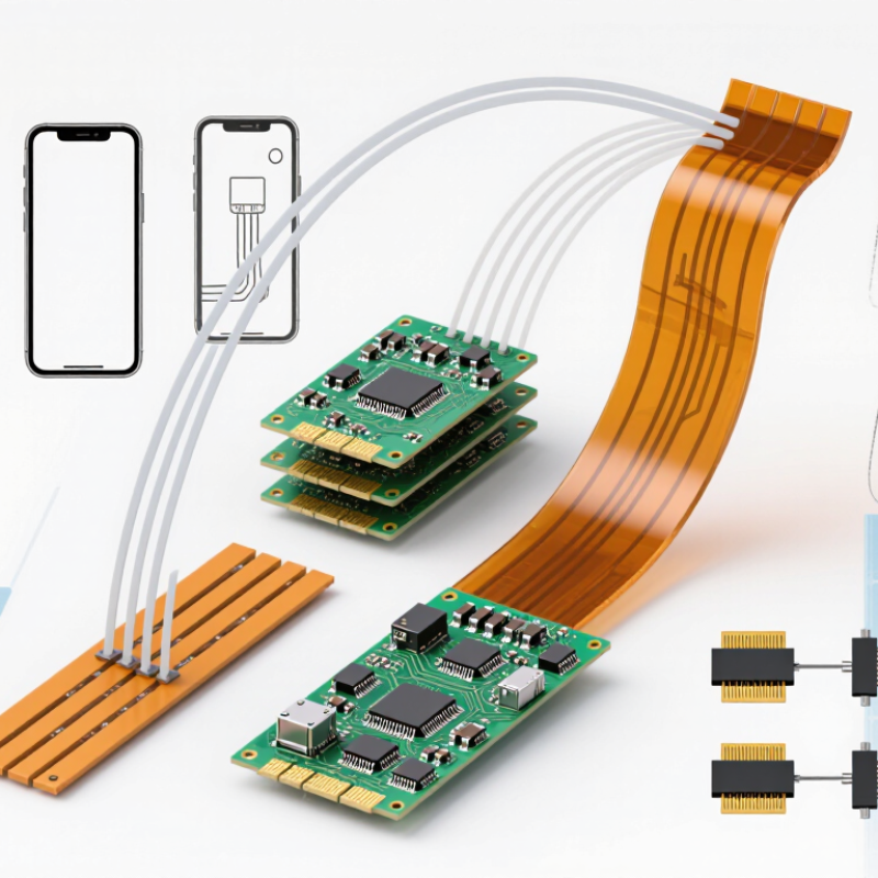
Multilayer flex circuits stack three or more conductive layers, often with insulating films between them. They support dense routing and complex connections in devices with limited space. Think of a folded medical sensor assembly or a compact camera module. But more layers usually mean greater thickness, tighter manufacturing tolerances, and higher cost. The choice is not always obvious. Compare the required bend radius, layer count, signal needs, and expected flex cycles with a fabricator before fixing the design. If the circuit stays mostly still after installation, a multilayer build may add complexity without solving a real problem.

Copper, Polyimide, and Adhesive: Materials That Shape Flex Performance

What Is the Best Type of Flex Circuit Board in 2026?
Copper, Polyimide, and Adhesive: Materials That Shape Flex Performance

There is no single best flex circuit material stack for every device. Copper carries the signal, but its temper and thickness affect how well a circuit tolerates repeated bending. Rolled-annealed copper is often preferred for dynamic flex, while electrodeposited copper can suit less demanding bends. Thinner copper can improve flexibility, but may increase resistance. That trade-off is easy to miss.

Polyimide provides electrical insulation and handles heat from assembly and operation. Its thickness influences stiffness, so a design that bends comfortably on screen may feel quite different near a connector or stiffener. Check the actual bend radius and layer stack, not just the material datasheet. Small geometry details matter.

Adhesive bonds copper to the insulating film in many constructions. It can add thickness and affect heat transfer, flexibility, and long-term bond stability. Adhesive-less laminates avoid that bonding layer, but they are not automatically the right choice for every cost or fabrication target. Not always. In practice, the best stack depends on bend cycles, available space, current load, and assembly temperatures. A prototype should be flexed in its real enclosure; bench samples can hide pinch points and uneven strain. I would revisit any assumption based only on nominal material properties. Short tests can reveal surprises.

Static-Bend Design: IPC-2223 Guidance Starts at 6× Thickness for Single-Sided Flex

For a single-sided flex circuit intended to bend once during installation and then remain still, IPC-2223 guidance commonly starts with a bend radius of at least six times the finished circuit thickness. This is a starting point, not a guarantee. A 0.20 mm-thick flex, for example, suggests a minimum radius near 1.2 mm. Check how the drawing defines the radius, since inside radius and other measurement conventions can differ.

A gentle curve matters. Avoid creases, sharp corners, and pressure from nearby fasteners. Keep the bend area free of solder joints and abrupt changes in copper width where the layout allows. Copper type, coverlay, adhesive, and the neutral-axis position all affect strain. In practical design reviews, measuring the completed stack-up can reveal differences from the nominal thickness listed in early drawings.

The six-times rule is useful, but not magic. A one-time assembly bend is different from repeated movement in service. If the circuit will flex often, six times may be too tight; use a larger radius and validate the design with material-specific guidance and bend testing. Real parts can behave imperfectly, especially when tolerances stack up.

What Is the Best Type of Flex Circuit Board in 2026?

Static-Bend Design: IPC-2223 guidance starts at 6× thickness for single-sided flex.

The bars show the 6× starting-point bend radius for several flex thicknesses. For example, a 0.20 mm flex thickness corresponds to a 1.20 mm radius. These values are calculated from the stated ratio; confirm the appropriate design limit for the specific material stack-up and application.

Dynamic-Bend Design: Repeated Motion Commonly Requires a Radius of 100× Thickness

What Is the Best Type of Flex Circuit Board in 2026?

For a circuit that bends repeatedly, dynamic-flex design matters more than choosing the thinnest board. A common starting point is a bend radius of at least 100 times the finished circuit thickness. IPC-2223, the industry design standard for flexible printed boards, provides guidance for flex construction and bend geometry. Treat the 100× figure as a design rule, not a guarantee: copper type, layer count, and adhesive thickness all affect fatigue life.

Picture a 0.2 mm flex tail moving inside a small hinge. A 20 mm radius is the 100× starting point; a tighter curve can concentrate strain near the copper. Keep traces away from the bend’s outer edges, avoid plated-through holes in the moving zone, and use rolled-annealed copper where repeated flexing is expected. IPC-2223 guidance should be checked against the actual stack-up and motion path. That detail is easy to miss.

A static installation can tolerate a much tighter bend than a cable that cycles thousands of times. Test a representative assembly through its real travel, temperature, and cycle count; a flat coupon cannot capture every hinge or housing constraint. The 100× rule is useful, but it is imperfect. Real motion is messy.

Selection Criteria: Compare Bend Life, Circuit Density, and Manufacturing Cost

The best flex circuit depends on what the board must survive. A 2024 market estimate from Fortune Business Insights valued the global flexible printed circuit board market at about US$27.7 billion in 2023. That growth reflects varied uses, not one universally superior construction. For repeated movement, prioritize rolled-annealed copper, a suitable polyimide stack, and a generous bend radius. IPC-2223 design guidance is a useful reference, but actual bend life depends on thickness, copper, radius, and test conditions. No magic cycle number.

Circuit density pushes designers toward finer traces and multilayer builds. Yet extra layers can increase stiffness and complicate bending, especially near a connector or a sharp fold. Keep dense routing outside the moving zone where possible. For a mostly static fold, a simpler single- or double-sided circuit may be enough. Manufacturing cost follows the details: layer count, copper type, coverlay openings, and tight registration tolerances all affect yield. The cheapest drawing may not be the cheapest production run.

Tips: Mark static and dynamic bend areas on the drawing. Ask the fabricator for a bend-life test using your actual radius and motion profile. Compare quotes by finished yield, not unit price alone. One caveat: early estimates often miss assembly constraints, so leave room to revise the stack-up.

What Is the Best Type of Flex Circuit Board in 2026? — Selection Criteria: Compare Bend Life, Circuit Density, and Manufacturing Cost

Typical design-level comparison. Actual performance and pricing depend on materials, copper type and thickness, geometry, order volume, and fabrication capability.

Flex Circuit Type Typical Construction Bend Life Considerations Circuit Density Relative Manufacturing Cost Best-Fit Applications
Single-Sided Flex One copper layer on a flexible dielectric, usually with a protective coverlay. Best suited to repeated dynamic bending when designed with rolled-annealed copper, generous bend radius, and suitable strain relief. Cycle life must be validated for the final design. Low to moderate; one conductive layer limits routing options but supports compact, lightweight circuits. Low; typically the most economical flex construction. Simple interconnects, moving assemblies, cameras, printers, and compact consumer devices.
Double-Sided Flex Two copper layers with plated through-holes connecting the layers. Suitable for occasional flexing or controlled movement. Vias and added copper can reduce fatigue life in bend regions; keep them out of dynamic bends where possible. Moderate to high; two routing layers provide more connectivity in a limited area. Medium; added copper, drilling, and plating increase process complexity. Compact assemblies that need more routing than a single layer, including modules with limited movement.
Multilayer Flex Three or more copper layers laminated with flexible dielectric and bonded layers. Generally best for static or low-cycle flexing. Greater thickness and internal layer structure usually make repeated tight-radius bending more demanding. High; multiple layers support dense routing, crossings, and complex interconnections. High; lamination, registration, and yield requirements add cost. Space-constrained equipment requiring complex routing, such as medical, aerospace, and instrumentation assemblies.
Rigid-Flex Rigid circuit sections joined by flexible sections within one integrated assembly. Flex sections can support repeated movement when specifically designed for it. Bend zones need controlled geometry, suitable copper, and freedom from vias and components. High overall; rigid areas can carry dense components while flex sections connect them. Very high; combines rigid and flexible processing and often requires more complex assembly planning. Compact products with multiple boards, reliable interconnect needs, or three-dimensional packaging constraints.

Selection guidance: For frequent movement and cost control, start with a single-sided flex design. Choose double-sided or multilayer flex when routing density justifies the added complexity. Select rigid-flex when integrated packaging or interconnect reliability outweighs its higher cost. Bend life is application-specific; confirm it through manufacturer review and cycle testing.

MSIRobot