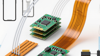
Global sourcing is reshaping how manufacturers design, assemble, and scale compact electronic products. Flex PCB assembly supports this shift with lightweight circuits, controlled bending, and fewer interconnects. These advantages matter in smartphones, medical sensors, automotive displays, and industrial wearables. A rigid board may occupy 3 millimeters of vertical space. A properly designed flexible circuit can fold around that constraint.
Industry data supports the opportunity. Fortune Business Insights reported that the global flexible electronics market reached approximately USD 29.27 billion in 2023. Its report projects growth to about USD 61.68 billion by 2032. This expansion reflects demand for thinner devices and integrated electronics. The IPC standards framework also provides practical guidance for design, fabrication, and assembly quality. IPC-2223 addresses flexible printed board design, while IPC-A-600 and IPC-A-610 support inspection and acceptance decisions. These references help sourcing teams compare suppliers using evidence, not attractive brochures.
Still, global sourcing is not automatically efficient. Material substitutions, copper thickness, bend radius, and adhesive selection can change performance. Small process differences may become visible after thousands of flexing cycles. That is where supplier experience becomes valuable. A capable partner should explain stack-up choices, provide test records, and manage traceability across production sites. The picture is promising, but not perfectly clean. Cost comparisons can also mislead when tooling, inspection, shipping, and redesign risks are excluded. Choosing flex pcb assembly therefore requires technical judgment, verified data, and honest communication from prototype through volume production.
Flex PCB assembly is the process of mounting electronic components onto a flexible printed circuit board. Unlike rigid boards, it uses thin, bendable materials that can fold, twist, or fit inside narrow spaces. This structure supports compact devices, moving controls, medical instruments, and lightweight industrial equipment.
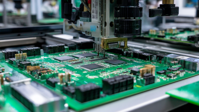
During assembly, technicians place components, apply solder, and inspect each connection. Controlled temperature profiles help protect the flexible substrate from warping. Engineers also check bend radius, copper thickness, connector strength, and repeated-motion performance. These details matter during global sourcing because transport, storage, and final installation may involve different handling conditions. A reliable supplier should provide inspection records, material specifications, and clear process controls.
Flex assembly can reduce wiring, save space, and improve mechanical reliability. It is not automatically the cheapest option. Poor layout decisions may create stress near solder joints or sharp corners. I have seen small design changes prevent larger production problems, but testing remains essential. Prototype bending tests, electrical checks, and thermal inspections can reveal weaknesses before volume production. Communication also needs care. Different teams may interpret drawings, tolerances, or acceptance standards differently. Clear documentation reduces that risk. Flex PCB assembly works best when design engineering, manufacturing, and quality teams review the product together.
Flex PCB assembly mounts electronic components on a flexible printed circuit board, allowing the circuit to bend, fold, or move within a product. The chart shows typical minimum bend-radius guidelines expressed as multiples of the finished flex-circuit thickness.
Typical starting guidance based on IPC-2223 design practices: approximately 10× thickness for static flexing and 100× thickness for dynamic flexing. Final values depend on layer count, copper type, materials, bend direction, and the required flex-cycle life.
Flex PCB assembly supports global sourcing by reducing weight, packaging volume, and mechanical constraints. A 2024 Grand View Research analysis estimated the global flexible printed circuit board market at approximately USD 26.7 billion in 2023. It also projected strong growth through 2030. That growth reflects demand for compact electronics, wearable devices, vehicles, and medical equipment. For sourcing teams, flexible circuits can replace several rigid interconnects with one bendable assembly. Fewer connectors may simplify procurement and reduce assembly steps.
Practical sourcing depends on repeatable specifications. Suppliers can follow IPC-2223 design guidance and IPC-A-600 acceptance criteria across different production regions. Digital manufacturing files, controlled impedance notes, and material certificates help engineers compare quotations fairly. A 0.15-millimeter polyimide circuit can arrive on a small reel, while stiffeners reinforce the connector area. This detail matters when shipments cross borders and handling conditions vary. The World Semiconductor Trade Statistics forecast also shows how globally distributed electronics demand continues to influence component planning and capacity decisions.
The process is not flawless. Flex circuits need careful bend-radius control, and rushed designs can create hidden copper fatigue. One gap remains. Not every supplier measures dynamic bending consistently. Sourcing teams should request bend-cycle evidence, cross-section reports, and lot-level traceability before approving production. Regional inspection plans can also catch delamination, exposed copper, or connector damage before final assembly. These checks require time, but they make global sourcing more dependable.
Why Choose Flex PCB Assembly for Global Sourcing?
Key Benefits of Flexible Circuit Manufacturing
Flexible circuit manufacturing supports compact products with fewer mechanical connections. In global sourcing, this can reduce assembly space, shipping weight, and connector-related failures. A flex PCB can fold around corners, fit inside narrow housings, or connect moving sections without bulky cables. That freedom helps designers create thinner medical instruments, sensors, and industrial controls.
The first layout is rarely perfect. Engineers must review bend radius, copper thickness, and stiffener placement before tooling. These details directly affect production yield and service life. Polyimide materials tolerate repeated movement, while carefully controlled copper patterns support stable electrical performance. Laser drilling, precision etching, and automated optical inspection help maintain consistent circuit geometry. Sample testing should include bending, thermal cycling, and solder-joint inspection.
Manufacturing records also matter. Reliable suppliers should provide traceability for materials, process parameters, and inspection results. Clear documentation makes international quality reviews easier. It also exposes weak points before mass production. Flexible circuits can reduce connectors and simplify final assembly, but they require disciplined design rules. A tight bend may cause copper fatigue. An oversized stiffener may prevent proper installation. Designers sometimes optimize the circuit but overlook the enclosure. Early fit checks can prevent expensive revisions, although they may slow the first prototype cycle.
Supplier selection determines more than unit price. It affects bend life, delivery stability, and field reliability. McKinsey’s “Risk, Resilience, and Rebalancing in Global Value Chains” reported that 93% of supply-chain leaders planned resilience actions. Flex PCB buyers should apply that lesson before production begins. Review the supplier’s experience with polyimide materials, fine-pitch assembly, dynamic bending, and controlled impedance. Ask for recent yield data, not only attractive samples. IPC standards, including IPC-2223 and IPC-A-610, can support consistent design and inspection requirements.
Tips: Request a capability matrix, process flow, sample inspection report, and corrective-action history. Check whether the supplier controls drilling, lamination, soldering, cleaning, and final testing internally. Confirm traceability for lots, operators, materials, and inspection records. Evaluate dual-source options for critical components. Logistics matter too. The World Bank’s 2023 Logistics Performance Index shows clear differences in customs efficiency, infrastructure, and shipment reliability across markets.
Be careful with promises.
A supplier may claim global capacity but outsource key processes. That can weaken accountability during a defect investigation. Review factory capacity by month, not by annual marketing figures. Also examine engineering support during DFM reviews and pilot builds. A cheaper quotation may hide tooling charges, rework, or longer approval cycles. I would still challenge my own scoring model. A perfect spreadsheet cannot measure every communication delay, cultural misunderstanding, or late engineering change. Ask for a small pilot order, then compare actual yield, response time, packaging quality, and delivery performance against the written proposal.
Selecting the right global flex PCB partner requires more than comparing unit prices. Start with engineering evidence. Ask for controlled impedance data, bend-cycle results, copper thickness records, and microsection photographs. A capable supplier should explain stack-up choices in plain language.
IPC-2223 guidance helps evaluate flexible circuit design, while ISO 9001 certification supports process discipline. Still, certificates do not guarantee stable production. Review recent audit findings, corrective-action records, and first-article inspection results. Small details matter. Check whether the supplier can maintain registration after repeated bending, thermal cycling, and adhesive aging. This is where assumptions often fail.
Global execution also depends on logistics. The World Bank’s 2023 Logistics Performance Index assessed 139 economies across customs, infrastructure, shipment quality, and delivery timeliness. Use those dimensions when comparing manufacturing locations. UNCTAD’s 2024 Review of Maritime Transport confirms that more than 80% of global merchandise trade moves by sea, so a partner needs documented contingency plans, not optimistic promises. Request dual-source material options, regional buffer stock, and clear escalation contacts. A low quotation can hide expensive redesigns. It may also exclude tooling, yield loss, or engineering changes. Require a landed-cost model with freight, duties, inspection, and warranty exposure. Visit the factory when possible. Remote evidence is useful, but incomplete. A strong partner may still show weaknesses; transparent discussion of them is more valuable than a flawless presentation.
| Evaluation Dimension | Relevant Flex PCB Data | Why It Matters for Global Sourcing | Recommended Partner Requirement | How to Verify |
|---|---|---|---|---|
| Space and Weight Reduction | Flexible circuits can replace multiple wire assemblies and support three-dimensional routing in compact products. | Lower wiring complexity can reduce enclosure size, assembly steps, and the number of mechanical connections. | Design-for-assembly capability Supplier should provide stack-up, bend-zone, and component-clearance reviews. |
Request a detailed design review showing layer count, finished thickness, bend zones, and connector locations. |
| Flex Construction | Common constructions include single-sided, double-sided, and multilayer flexible circuits. Stiffeners are frequently added beneath connectors or component areas. | The construction affects flexibility, routing density, manufacturing yield, and assembly cost. | Ability to manufacture the required layer count, coverlay, stiffener, adhesive, and surface-finish combination. | Compare the supplier's capability matrix with the released fabrication drawing and material specification. |
| Material Selection | Polyimide is widely used for flex circuits because it offers flexibility and thermal stability. Copper type and thickness must match the electrical and bending requirements. | Incorrect materials can cause cracking, delamination, impedance variation, or premature failure during repeated flexing. | Controlled material sourcing, traceability, and documented approval of equivalent materials. | Review material certificates, lot traceability, and the supplier's approved-material list. |
| Minimum Bend Radius | For many static-bend designs, a commonly used starting point is approximately 6–10 times the finished flex thickness. Dynamic applications require design-specific validation and may need a larger radius. | A suitable bend radius helps prevent copper fatigue, cracking, and coverlay damage. | Supplier must review static or dynamic bending conditions before quoting and production. | Provide bend radius, bend angle, bend cycles, operating temperature, and assembly-motion data. |
| Dynamic Flexing Capability | Repeated-flex applications require specialized copper patterns, bend-zone layout, strain relief, and cycle testing. There is no universal cycle rating for every flex design. | Wearable, hinge, actuator, and moving-module products depend on validated flex life rather than visual inspection alone. | Engineering support for accelerated life testing using the actual bend radius, speed, stroke, and load. | Request a test plan, sample results, failure criteria, and the number of completed flex cycles. |
| Assembly Technology | Flex PCB assembly may include surface-mount technology, fine-pitch components, connectors, stiffeners, and selective reinforcement. | Flex material can move or deform during printing and reflow, so specialized fixtures and process controls are important. | Documented flex handling, temporary carrier, fixture, solder-paste, reflow, and inspection procedures. | Audit process instructions and review first-article assembly records, including fixture and profile data. |
| Thermal Process Control | Reflow temperature must be compatible with the selected flex materials, coverlay, adhesive system, components, and surface finish. | Uncontrolled thermal exposure may lead to warpage, delamination, solder defects, or component damage. | Profile measurement for production runs and documented control of preheat, peak temperature, and cooling rate. | Request thermal-profile reports and confirm that the process window matches component and material specifications. |
| Quality Standards | IPC-2223 provides design guidance for flexible printed boards, while IPC-6013 covers qualification and performance requirements for flexible and rigid-flex printed boards. | Recognized standards create a common technical language for drawings, inspection, qualification, and acceptance criteria. | Ability to build and inspect according to the applicable IPC class and customer workmanship requirements. | Include the required IPC class, acceptance criteria, and inspection method in the purchase documentation. |
| Inspection Coverage | Typical controls may include automated optical inspection, electrical testing, dimensional inspection, solder-joint inspection, and sample-based microsection analysis. | Inspection coverage reduces the risk of open circuits, shorts, misalignment, solder defects, and dimensional problems. | Inspection plan linked to critical-to-quality characteristics and traceable test records. | Review control plans, test coverage, defect criteria, calibration records, and corrective-action reports. |
| Electrical Testing | Flying-probe testing is useful for lower-volume or changing designs, while fixture-based testing is generally more efficient for stable, higher-volume production. | The test approach affects tooling cost, throughput, coverage, and production flexibility. | Supplier should recommend a test method based on quantity, complexity, net count, and change frequency. | Confirm test coverage, fixture ownership, program responsibility, retest rules, and reporting format. |
| Impedance and Signal Integrity | Controlled-impedance flex designs require appropriate stack-up data, dielectric thickness control, copper geometry, and test coupons where applicable. | Stable impedance is important for high-speed interfaces and helps reduce signal-reflection risk. | Fabrication stack-up review, impedance calculation, coupon strategy, and documented tolerance control. | Request the final stack-up, impedance report, coupon results, and any approved deviation records. |
| Supply Chain Traceability | Traceability should cover laminate, copper, solder materials, components, assembly lots, inspection results, and shipment records. | Traceability supports root-cause analysis, regulatory inquiries, field containment, and controlled global replenishment. | Lot-level records with defined retention periods and a documented nonconformance process. | Perform a sample traceability exercise from finished assembly back to material and component lots. |
| Prototype and Production Support | Prototype builds typically require more engineering interaction, while production requires repeatable tooling, documented processes, and capacity planning. | A partner that supports both stages can reduce redesign risk during the transition to volume manufacturing. | Clear process for design-for-manufacturing feedback, engineering-change control, pilot builds, and ramp-up. | Ask for sample project documentation, engineering-change workflow, and pilot-to-production transition criteria. |
| Lead-Time Planning | Actual timing depends on layer count, materials, component availability, testing, tooling, approvals, and order quantity. Prototype and production schedules should be quoted separately. | Transparent planning helps coordinate international logistics, product launches, and safety-stock decisions. | Written milestone schedule covering engineering review, fabrication, component procurement, assembly, inspection, and shipment. | Compare quoted milestones with historical delivery performance and require advance notice for schedule risks. |
| International Logistics | Important variables include shipping terms, export documentation, customs classification, packaging, moisture protection, and shipment tracking. | Well-defined logistics reduce border delays, transit damage, and uncertainty in production planning. | Documented packaging specification, shipment responsibility, export documentation process, and contingency options. | Confirm Incoterms, packaging validation, carrier arrangements, tracking procedures, and customs-document ownership. |
| Total Cost of Ownership | Total cost includes tooling, fabrication, components, assembly, testing, packaging, freight, duties, engineering changes, and quality-related costs. | The lowest quoted unit price may not provide the lowest delivered or lifecycle cost. | Transparent quotation with separate one-time, recurring, logistics, and optional-service charges. | Compare suppliers using the same bill of materials, annual volume, delivery terms, test coverage, and quality requirements. |
| Partner Selection Score | A practical assessment can score technical capability, quality system, delivery reliability, communication, scalability, risk control, and total cost. | A weighted evaluation prevents price from outweighing critical technical and supply-chain risks. | Use a documented scorecard with minimum pass criteria for quality, compliance, engineering, and delivery. | Conduct a technical audit, sample review, reference-project assessment, and controlled pilot order before full release. |
MSIRobot