Icon about-block-ico-1 Icon about-block-ico-2 Icon about-block-ico-3 Icon about-block-ico-4 Icon announcement-close Icon arrow-left Icon arrow-right Icon arrow-sm Icon asterisk Icon banner-transparent-vector Icon btn-callback-ico Icon careers-item-location Icon careers-item-time Icon careers-item-type Icon careers-mail-ico Icon careers-phone-ico Icon careers-search-ico Icon careers-single-hero-vector Icon careers-single-more-vector Icon careers-vector Icon check Icon close Icon dfm-image-left-vector Icon dfm-image-right-vector Icon document Icon download-popup-vector Icon dropdown Icon envelope Icon facebook Icon faq-banner-bg Icon faq-title-ico-active Icon faq-title-ico Icon featured-links-block-bg Icon figure-1 Icon figure-10 Icon figure-11 Icon figure-12 Icon figure-13 Icon figure-14 Icon figure-15 Icon figure-2 Icon figure-3 Icon figure-4 Icon figure-5 Icon figure-6 Icon figure-7 Icon figure-8 Icon figure-9 Icon file-upload Icon form-sidebar-back Icon form-step-done Icon gmap-marker-group-icon Icon gmap-marker-icon Icon header-profile-ico Icon instagram Icon link Icon linkedin Icon loader Icon mail Icon phone Icon play-yt Icon play Icon post-nav-arr-left Icon quote-banner-vector Icon quote-block-aside-vector Icon quote-contact-phone-ico Icon quote-contact-position-ico Icon sidebar-location Icon sidebar-phone Icon technology-banner-nav-left-vector Icon technology-banner-nav-right-vector Icon twitter Icon webinar-item-date-vector Icon whitepaper-img-ico-left Icon whitepaper-img-ico-right Icon whitepapers-listing-banner-ico Icon whitepapers-single-aside-vector Icon youtube Icon yt-play-button

How to Design a Flex Circuit for Your Electronics Project?

Designing a flex circuit for your electronics project can be a rewarding yet challenging task. A flex circuit is a unique solution that allows for more compact designs. Its adaptability makes it ideal for projects where space is limited. With the right approach, you can create flexible electronics that perform well in various applications.

In the design process, consider factors like material selection and circuit layout. Flex circuits require careful planning to ensure functionality and durability. It can be daunting when faced with multiple layers and connections. Mistakes in design can lead to failures, demanding revisions and deeper insights. Every step of the way presents opportunities for learning and improvement.

Keep in mind that each project is different. Flex circuits can be intricate; simplicity can sometimes be overlooked. Reflect on your motivations and the overall purpose. As you navigate through the design, embrace the flaws and uncertainties. Learning from these moments can lead to innovative solutions in your future projects.

How to Design a Flex Circuit for Your Electronics Project?

Understanding the Basics of Flex Circuits in Electronics Design

Flex circuits are an innovative solution in electronic design. They consist of flexible materials that allow circuits to bend and twist. This versatility opens up new design possibilities for compact and intricate electronic devices. However, understanding their construction is vital.

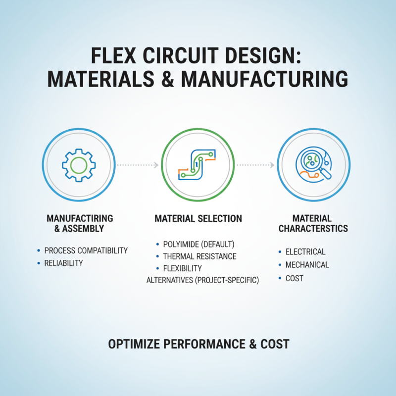
Flex circuits typically consist of conductive traces made from copper, laminated on a flexible base material. They can be single-sided, double-sided, or even multi-layered. Choosing the right base material is crucial. Different polymers offer various thermal and mechanical properties. A common mistake is overlooking the thermal impact on the circuit layers during soldering.

Designing a flex circuit also involves careful consideration of the layout. Ensure traces are wide enough to handle the current. A common error is designing traces that are too narrow for high power applications, leading to overheating. Testing prototypes is essential. Sometimes, the circuit might not perform as expected. Adjustments in layout or material can make a significant difference. Embrace trial and error; it is part of the design process.

Key Considerations for Flex Circuit Material Selection

When selecting materials for flex circuits, the options can seem overwhelming. It's essential to consider several factors such as flexibility, durability, and thermal performance. Polyimide is popular for its excellent thermal stability. Yet, it may not be the best for all applications. Some projects might require different materials based on specific environmental conditions.

Another key aspect is the thickness of the substrate. A thinner substrate often enhances flexibility. However, it could compromise the circuit’s durability. Sometimes, engineers overlook this balance. Choosing the right copper thickness is also critical. Thinner copper layers are lighter but can lead to increased resistance. This trade-off must be evaluated carefully.

Adhesive selection also plays a crucial role. The adhesive needs to withstand various stresses without degrading. Yet not all adhesives perform well in high humidity or temperature. This area often requires testing and iteration. Flex circuits offer great benefits, but careful material selection ensures their effectiveness in your project. The right choice can significantly affect performance and longevity.

Flex Circuit Material Selection: Key Considerations

Step-by-Step Process for Designing a Flex Circuit Layout

Designing a flex circuit involves several critical steps. Begin by defining your project requirements. Determine the size, shape, and complexity of the circuit. Flex circuits can fit in tight spaces and are ideal for wearable tech. According to the IPC 2223 standard, the thickness for standard flexible PCB materials typically ranges from 0.2 mm to 0.5 mm. Choose materials wisely to ensure conductivity and flexibility.

Next, create a schematic. This is a crucial part of the design. By using CAD software, you can visualize the circuit layout. Precision in this step is vital. An error here could lead to circuit failure. A report by Research and Markets suggests a growth rate of 13% for flexible electronics, emphasizing the importance of accuracy in design. Pay attention to trace widths and pad sizes, as these factors directly affect performance.

Finally, consider thermal management. Flex circuits can generate heat, impacting their effectiveness. An uneven distribution of heat can lead to failures. Make sure to include vias where necessary. Reflect on your design choices throughout the process. Flexibility in design is essential, but so is reliability. Don’t overlook the testing phase. Validate your layout before moving on to production.

Techniques for Testing and Validating Your Flex Circuit Design

Testing and validating your flex circuit design is crucial for ensuring reliability. Start with a prototype. Create a sample that closely resembles your final design. This helps identify any potential issues early on. Visual inspection is a simple yet effective first step. Look for any visible defects or misalignments. Regularly checking the solder joints is also important. A weak connection can lead to circuit failure.

Next, perform electrical tests. Use a multimeter to check resistance and continuity. Testing for shorts is essential, as it can prevent damaging components. Functional testing should follow. Subject your flex circuit to the conditions it will face in real applications. Monitor performance and signal integrity throughout the tests. This phase often reveals hidden flaws. You might encounter unexpected noise or interference.

Documentation plays a key role in validation. Keep track of all tests and results. This helps in understanding failures and improving future designs. Review your testing process critically. Ask if any areas can be enhanced. Create an iterative loop: test, modify, and retest. Embrace imperfections as learning opportunities, guiding you toward more robust flex circuit designs.

How to Design a Flex Circuit for Your Electronics Project? - Techniques for Testing and Validating Your Flex Circuit Design

Parameter Description Recommended Value Test Method
Thickness Total thickness of the flex circuit 0.2 mm to 0.5 mm Micrometer measurement
Bend Radius Minimum bend radius of the circuit 1.5 times the thickness Visual inspection
Trace Width Width of the conductive traces 0.1 mm to 0.3 mm Caliper measurement
Dielectric Material Material used for insulation Polyimide Material testing
Impedance Control Control of the electrical impedance 50 ohm for RF applications TDR (Time Domain Reflectometry)
Flexibility Tests Tests to evaluate bending performance >100,000 cycles Bending test machine

Best Practices for Manufacturing and Assembling Flex Circuits

How to Design a Flex Circuit for Your Electronics Project?

When designing a flex circuit, careful attention to manufacturing and assembly is crucial. It's important to select the right material. Polyimide is widely used due to its excellent thermal resistance and flexibility. However, consider alternatives based on your project needs. Each material has its own characteristics, which can affect performance.

**Tip:** Use CAD software to design the layout. This helps in visualizing how components fit. Ensure proper spacing between traces. Too close can cause shorts. However, having too much space can increase the circuit size unnecessarily.

For assembly, avoid excessive bending during installation. Mistakes can lead to fracture, which may be irreversible. Taking the time to think through the assembly process is vital. Training personnel on handling flex circuits is often overlooked but should not be.

**Tip:** Consider using automated assembly methods. They improve consistency and reduce human error. Yet, monitor the process closely. Sometimes, machines make mistakes too. A balance between human oversight and automation is essential.

MSIRobot