
What Are the Top Types of Digital Signal Isolators?
Digital systems often need to exchange data across electrical boundaries without sharing a direct conductive path. A Digital Signal Isolator provides that separation while preserving logic-level communication between circuits. In a motor drive, for example, it can carry control pulses from a low-voltage processor to circuitry exposed to fast switching transients. The isolator helps protect sensitive electronics, but it does not remove every design risk. Layout, power, and noise still matter.
Common approaches include capacitive and magnetic coupling, while optical isolators are often considered alongside them. Capacitive devices transfer changing signals through an electric field. Magnetic designs use transformer-like coupling. Optical types transmit data as light, typically using an LED and detector. Each approach has tradeoffs. Some designs prioritize compact size or low power; others suit demanding transient environments. No type is best for every circuit.
Choosing among them means looking beyond the headline data rate. Engineers also compare channel count, propagation delay, common-mode transient immunity, insulation ratings, and operating conditions. A noisy inverter may call for different priorities than a small sensor board. Datasheets help, but real circuit behavior can still surprise designers. The following overview compares the main isolator types, explains where each tends to fit, and highlights practical details worth checking before selecting a component.
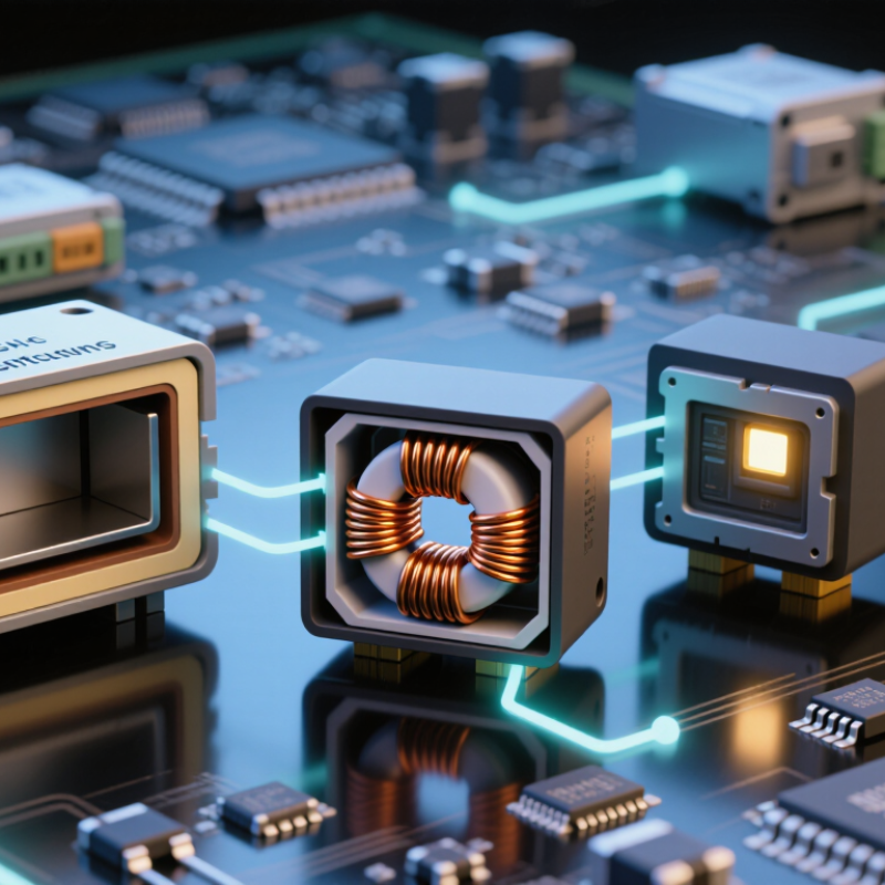
Digital Signal Isolators: Signal Paths, Isolation Barriers, and Key Ratings
What Are the Top Types of Digital Signal Isolators?
Digital Signal Isolators: Signal Paths, Isolation Barriers, and Key Ratings
A digital isolator carries logic signals across a barrier while keeping input and output circuits electrically separated. Capacitive devices transfer encoded signals through an electric field. Magnetic types use a changing magnetic field, while optical isolators pass light across the gap. Each approach has different design trade-offs, including power use, speed, and susceptibility to interference.
Inside the signal path, an input circuit conditions the logic level, encodes its transitions, and sends them across the barrier. A receiver reconstructs the output. The barrier itself may use insulating layers within the package, but the signal still needs a clean path. Fast voltage changes nearby can disturb that path. That matters.
Compare ratings in the context of the application. Data rate and propagation delay affect timing; common-mode transient immunity, or CMTI, indicates resistance to rapid voltage changes across the barrier. Isolation voltage is not the same as continuous working voltage. I would not choose by headline voltage alone. Check creepage and clearance, channel direction, and required safety approvals against the equipment design. Datasheets can make these checks look simpler than they are. A few millimeters of board space may change the practical choice.