Icon about-block-ico-1 Icon about-block-ico-2 Icon about-block-ico-3 Icon about-block-ico-4 Icon announcement-close Icon arrow-left Icon arrow-right Icon arrow-sm Icon asterisk Icon banner-transparent-vector Icon btn-callback-ico Icon careers-item-location Icon careers-item-time Icon careers-item-type Icon careers-mail-ico Icon careers-phone-ico Icon careers-search-ico Icon careers-single-hero-vector Icon careers-single-more-vector Icon careers-vector Icon check Icon close Icon dfm-image-left-vector Icon dfm-image-right-vector Icon document Icon download-popup-vector Icon dropdown Icon envelope Icon facebook Icon faq-banner-bg Icon faq-title-ico-active Icon faq-title-ico Icon featured-links-block-bg Icon figure-1 Icon figure-10 Icon figure-11 Icon figure-12 Icon figure-13 Icon figure-14 Icon figure-15 Icon figure-2 Icon figure-3 Icon figure-4 Icon figure-5 Icon figure-6 Icon figure-7 Icon figure-8 Icon figure-9 Icon file-upload Icon form-sidebar-back Icon form-step-done Icon gmap-marker-group-icon Icon gmap-marker-icon Icon header-profile-ico Icon instagram Icon link Icon linkedin Icon loader Icon mail Icon phone Icon play-yt Icon play Icon post-nav-arr-left Icon quote-banner-vector Icon quote-block-aside-vector Icon quote-contact-phone-ico Icon quote-contact-position-ico Icon sidebar-location Icon sidebar-phone Icon technology-banner-nav-left-vector Icon technology-banner-nav-right-vector Icon twitter Icon webinar-item-date-vector Icon whitepaper-img-ico-left Icon whitepaper-img-ico-right Icon whitepapers-listing-banner-ico Icon whitepapers-single-aside-vector Icon youtube Icon yt-play-button

What Are Threaded Couplers and How Do They Work?

Threaded Couplers are compact mechanical components that connect two threaded rods, pipes, studs, or fittings. Their internal threads match the external threads of each connected part. When tightened, the coupler creates a continuous, aligned connection. Simple in appearance, they require careful selection.

In construction, plumbing, machinery, and structural work, these components help extend lengths or join separate sections. A steel coupler may connect reinforcing bars inside concrete. A brass version may join compatible pipe fittings. The connection depends on thread size, pitch, direction, material, and engagement length. Even a small mismatch can cause cross-threading, weak contact, or permanent damage.

The working principle is straightforward. Rotational force moves the threaded parts through the coupler. Tightening increases contact between the mating threads. This friction helps resist loosening under normal service conditions. However, friction alone is not always enough. Vibration, temperature changes, corrosion, and excessive loading can reduce reliability.

Experienced installers inspect the threads before assembly. They remove dirt, burrs, and damaged edges. A suitable lubricant may improve installation, but it must match the application. Some environments require locking compounds or additional retention methods. Manufacturer specifications and relevant industry standards should guide final decisions.

Not every failure is obvious. A connection may look secure while carrying uneven stress. This is why torque, alignment, and thread engagement deserve attention. In practice, mistakes happen, especially in crowded work areas. A careful inspection can prevent them. This guide explains how Threaded Couplers work, where they are used, and which details influence safe, dependable performance.
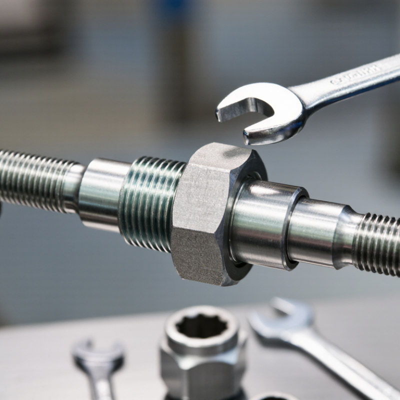
What Are Threaded Couplers and How Do They Work?

What Are Threaded Couplers?

Threaded couplers are mechanical connectors used to join reinforcing steel bars. Each bar receives a matching thread, either rolled directly onto the steel or formed after preparation. The coupler then engages both threaded ends, creating a continuous load path through the reinforcement. It replaces traditional lap splicing, which can consume valuable concrete space.

A coupler is not automatically better. Thread cleanliness, thread depth, alignment, and tightening torque affect performance. On site, an apparently secure connection may still fail inspection if the threads are damaged or insufficiently engaged. ISO 15835:2018 evaluates reinforcing-bar couplers through tensile, slip, and fatigue requirements. ACI 318-19 also recognizes mechanical splices when approved performance criteria are met. These standards make testing essential, not optional.

The need is practical. The Federal Highway Administration’s 2023 National Bridge Inventory records more than 617,000 U.S. bridges, many requiring repair within confined work zones. Couplers can simplify congested reinforcement and support prefabricated cage installation. Industry market analysis published in 2024 forecasts continued growth in mechanical rebar connection demand, driven by taller concrete structures and faster construction schedules. Still, installation quality remains the weak link. A detailed inspection log, calibrated tools, and verified mill certificates provide stronger assurance than appearance alone.

Key Components and Thread Designs

Threaded couplers connect two threaded parts and transfer force through their mating surfaces. Key components include the coupler body, internal or external threads, shoulder, and sealing surface. The body carries torque and protects the joint. Thread profiles control engagement, load transfer, and installation speed. Coarse threads assemble quickly and handle light contamination better. Fine threads offer precise adjustment and stronger engagement over a short length. A shoulder can control insertion depth. Threads alone rarely provide a dependable seal.

Thread designs must match the working conditions. Straight threads mainly hold components together, while tapered threads wedge tightly as they advance. Pitch, flank angle, crest shape, and root shape also affect performance. In field fitting, poor alignment often causes cross-threading. It damages the first threads and creates false tightness. I have seen joints feel secure, then loosen under vibration. Torque should follow verified engineering data, not guesswork. Thread gauges help, although worn gauges can mislead careful technicians.

Tips: Clean both thread surfaces before assembly. Start the coupler by hand. Never force it. Use a compatible lubricant when specified, because lubrication changes torque readings. Check shoulder contact and thread engagement visually. Avoid mixing thread standards, even when they appear similar. For hot, wet, or corrosive service, select materials and seals for that environment. Recheck the joint after initial operating cycles; this simple step is easy to overlook.

How Threaded Couplers Work Step by Step

Threaded couplers are hollow connectors with internal threads. They join two threaded rods, pipes, or fasteners along one continuous line. Their strength depends on thread quality, material, alignment, and engagement depth. A coupler should match the thread diameter, pitch, and profile exactly. A small mismatch can create damaging friction.

The process begins with cleaning both external threads. Dirt, rust, or metal chips can prevent full contact. The technician then checks the threads by hand and places the coupler over one end. It should turn smoothly without force. The second threaded part enters from the opposite side. Both parts must reach the required engagement depth. This transfers the load through the connected threads, rather than through the coupler’s middle section alone. A wrench may provide final tightening, but excessive force can stretch threads or deform the connector. Exact torque depends on the material, diameter, lubrication, and engineering instructions.

Inspection matters after assembly. Look for uneven gaps, damaged crests, cross-threading, or exposed threads beyond the acceptable limit. A coupler that feels tight is not automatically secure. That is a common mistake. Slight misalignment can hide inside a clean-looking connection. In demanding applications, technicians measure engagement and verify torque with calibrated tools. Some practical judgments remain imperfect, especially when corrosion obscures the thread profile. Careful rechecking is often safer than trusting appearance.

What Are Threaded Couplers and How Do They Work? — How Threaded Couplers Work Step by Step
Step Work Stage Component or Action How It Works Key Check or Result
1 Identify the connection Inspect the two threaded ends and the coupler A threaded coupler is a hollow fitting with internal threads, or a combination of internal and external threads, designed to join compatible threaded components. Confirm the thread standard, nominal size, thread direction, and gender. Threads should not be forced together if the pitch or profile differs.
2 Match thread specifications Compare diameter, pitch, and thread form The major diameter is the outside diameter of an external thread. Pitch is the distance between adjacent thread crests. Both must match the mating thread for proper engagement. For example, an M12 × 1.75 thread has a nominal diameter of 12 mm and a pitch of 1.75 mm.
3 Prepare the threads Clean the thread surfaces Dust, chips, corrosion, paint, or damaged thread crests can prevent full engagement and may cause cross-threading or leakage. Threads should be clean, free from burrs, and visibly undamaged. Remove loose contamination without altering the thread profile.
4 Apply sealing method Use a suitable sealant when required Parallel threads generally require a separate sealing element, such as an O-ring, gasket, or approved thread sealant. Tapered pipe threads can create a seal through wedging and controlled interference, but sealant may still be required by the application. The sealant must be compatible with the fluid, temperature, pressure, and material. Avoid applying excess sealant near passages or hydraulic systems.
5 Start by hand Align the components and rotate the coupler manually Hand-starting allows the thread crests and roots to align before torque is applied. The coupler should turn smoothly for several rotations without binding. Stop immediately if resistance occurs at the first thread or if the parts feel misaligned. This helps prevent cross-threading.
6 Engage the threads Turn the coupler until the required engagement length is reached As the threads advance, the helical surfaces convert rotational motion into axial movement. The mating flanks carry the load while the coupler keeps the connected parts aligned. Use the specified engagement length for the design. Engagement should be sufficient to transfer the expected tensile, shear, or pressure load.
7 Apply controlled torque Tighten with the specified tool and procedure Tightening torque creates a clamping force between the connected parts. The correct torque depends on thread size, material, lubrication, coating, and engineering requirements. Use a calibrated torque tool where a torque value is specified. Do not use a generic torque value for every material or application.
8 Secure the connection Install a locknut, retaining compound, safety wire, or other approved locking method if required Vibration, thermal cycling, and repeated loading can reduce preload and cause loosening. A locking method helps maintain the intended connection condition. Select the locking method according to the equipment design and service environment. Do not combine incompatible chemical products or locking devices.
9 Inspect the assembly Check alignment, exposed thread length, damage, and seal condition A visual and dimensional inspection confirms that the coupler is seated correctly and that the threads have not been stripped, deformed, or left partially engaged. Look for uniform seating, no visible gaps where a seal is required, no thread damage, and no excessive deformation of the coupler or connected parts.
10 Test under service conditions Perform a leak, pressure, load, or functional test as applicable The completed connection is evaluated under the conditions it is designed to withstand. The test method depends on whether the coupler is used for mechanical, hydraulic, pneumatic, structural, or instrumentation service. Verify that there is no leakage, unexpected movement, loosening, or abnormal deformation. Depressurize systems safely before making adjustments.
11 Maintain the connection Inspect periodically and retighten only when permitted Environmental exposure, vibration, corrosion, and repeated assembly can affect thread performance and sealing. Routine inspection helps identify degradation before failure. Replace components with stripped, cracked, heavily corroded, or permanently deformed threads. Follow the equipment maker’s maintenance procedure.
Engineering note: Threaded couplers are available in straight, reducing, union, and adapter configurations. Their load capacity and pressure suitability depend on thread geometry, material strength, engagement length, wall thickness, seal design, installation torque, and operating conditions.

Common Types of Threaded Couplers

Threaded couplers connect two threaded components without welding or permanent bonding. They are common in water lines, air systems, machinery, and structural assemblies. Their threads create mechanical engagement, while a seal prevents fluid or air from escaping. Correct selection depends on thread size, pitch, direction, material, and pressure rating. A connection can feel tight and still be wrong.

A straight female-to-female coupler joins two male threaded ends of the same diameter. It suits simple extensions and repairs. A reducing coupler joins different diameters, such as a larger inlet to a smaller branch. Male-to-female couplers change the connection gender and may solve limited-space problems.

A union-style threaded coupler allows one section to disconnect without turning the entire pipe. This matters near valves, filters, or fixed equipment. Full-thread versions provide deeper engagement, while short versions help in crowded assemblies.

Thread standards must match. Common systems include tapered and parallel threads, but they do not seal in the same way. Tapered threads often use approved sealant, while parallel threads usually need a gasket or sealing washer. Clean the threads before assembly. Start by hand, then tighten carefully with suitable tools. Excessive force can crack fittings or distort threads. Small leaks often reveal poor alignment, not inadequate tightening. Even experienced installers should verify thread compatibility twice; confidence sometimes hides a simple measurement error. Inspect the finished joint under working pressure and check it again after the system settles.

Applications and Selection Factors

What Are Threaded Couplers and How Do They Work?

Threaded couplers are mechanical connectors that join two threaded components. They transfer tension, compression, or rotational force through matching internal and external threads. When tightened, the threads create controlled contact between the connected parts. The coupler itself does not simply “hold” them together. Proper engagement and tightening provide the working strength.

Applications vary across construction, fabrication, maintenance, and equipment assembly. They can connect reinforcing bars, threaded rods, pipe sections, anchor systems, and structural components. In confined spaces, couplers are useful because they reduce the need for long overlaps or on-site welding. They also support cleaner installation when heat, sparks, or complicated access create practical problems. Field conditions still matter. Dust, damaged threads, and poor alignment can reduce performance.

Selection requires more than matching diameter. Check thread profile, pitch, material grade, load direction, corrosion exposure, and required movement. For outdoor or humid locations, corrosion-resistant materials may be necessary. High-load applications need documented strength ratings and verified installation procedures. The coupler should also fit available tools and clearance. A technically strong part can become unsuitable if workers cannot tighten it correctly. That detail is often overlooked. During inspection, confirm full thread engagement, clean contact surfaces, and visible damage. Torque values should follow approved engineering data, not guesswork. A perfect selection on paper may still fail when installation habits are inconsistent.

MSIRobot