
Why Choose the Right Drill Pipe for Your Project?
Choosing the right Drill Pipe can determine whether a drilling project runs smoothly or becomes an expensive sequence of delays. The pipe carries rotational force, drilling fluid, and heavy loads through demanding underground conditions. Its performance affects penetration speed, hole stability, equipment wear, and crew safety. A small mismatch can create large problems.
A suitable Drill Pipe must match the rig, borehole depth, formation hardness, and expected torque. Wall thickness, steel grade, tool joint design, connection type, and fatigue resistance all deserve careful review. Field engineers often compare manufacturer data with inspection records before approving a pipe string. They also examine thread condition, straightness, wear patterns, and previous service history. Numbers matter. So does evidence from real operating conditions.
Mud properties and temperature can change performance more than planning documents suggest. A pipe that works well in a shallow, stable formation may struggle in a deep, abrasive hole. The best selection is rarely the cheapest option. It balances service life, maintenance needs, availability, and total drilling cost. There is no perfect choice. Even experienced teams can overlook a connection detail or underestimate cyclic stress. That possibility deserves honest attention.
Reliable suppliers should provide traceable material certificates, clear specifications, and practical technical support. Independent inspection can add confidence before transportation and installation. Choosing carefully helps reduce unplanned trips, connection failures, and avoidable downtime. It also gives the crew a clearer basis for decisions when conditions change underground. Good planning is not dramatic. It is measurable, documented, and ready for revision.
Drill Pipe Basics: Purpose, Structure, and Key Components
Why Choose the Right Drill Pipe for Your Project?
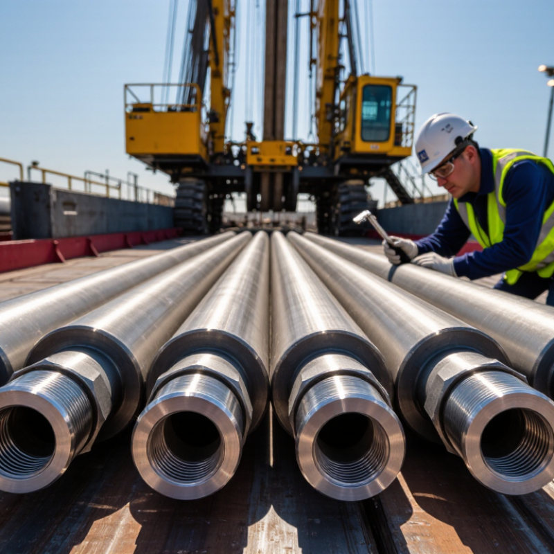
Drill pipe transfers rotation, torque, drilling fluid, and axial load between the rig and bit. Its structure looks simple, but every section carries a different duty. The pipe body provides flexibility and fluid passage. Tool joints create the threaded connection. The pin enters the box, while the upset adds metal around the joint for strength. Hardbanding protects the outer surface from abrasive contact with the borehole.
API Specification 5DP identifies common steel grades by minimum yield strength. Grade E provides 75 ksi, X offers 95 ksi, G reaches 105 ksi, and S reaches 150 ksi. These figures help engineers match pipe strength with depth, torque, and pressure conditions. The pipe’s internal diameter also affects hydraulic performance. A smaller passage increases fluid velocity, but it may raise pressure loss. The IADC Drilling Manual stresses that connection design, inspection, and operating limits must work together.
Field decisions should include wall thickness, tool-joint diameter, connection type, fatigue history, and expected dogleg severity. API RP 7G-2 recommends inspection practices for used drill stem components, including visual checks, dimensional measurements, and non-destructive testing. Small defects matter. A damaged thread can grow under repeated loading. I still see one weakness in many selection plans: they focus on tensile strength alone. That is incomplete. Temperature, vibration, corrosion, and poor make-up torque can change real performance. The best choice is not always the strongest pipe. It is the pipe whose structure, components, and verified condition fit the entire drilling cycle.
| Category | Key Component or Property | Typical Data or Specification | Why It Matters for Project Selection |
|---|---|---|---|
| Purpose | Primary function | Transfers rotary torque, axial force, and drilling fluid between the surface equipment and the drill bit. | The pipe must withstand the combined mechanical and hydraulic loads expected during drilling, not just the static weight of the string. |
| Pipe Body | Tubular steel section | A hollow, seamless or welded steel tube designed to carry drilling fluid through its internal bore. | Wall thickness, steel grade, and outside diameter affect strength, pressure capacity, weight, handling, and available internal flow area. |
| Tool Joint | Upset threaded connection | A thicker, high-strength connection at each pipe end, normally consisting of a pin and a box. | Tool joints provide the connection strength and wear resistance needed for repeated make-up, break-out, rotation, and contact with the borehole wall. |
| Connection | Thread profile | Common drilling connections use tapered, rotary-shouldered threads with a torque shoulder. | The connection must match the rest of the drill string. Thread incompatibility can cause leakage, poor torque transfer, or connection damage. |
| Dimensions | Outside diameter | Common oilfield drill pipe sizes include approximately 2⅜ to 6⅝ in outside diameter; exact sizes vary by application. | Diameter influences annular clearance, hydraulic velocity, buckling resistance, hole fit, and the maximum practical drilling depth. |
| Dimensions | Nominal length | Typical pipe stands are assembled from single joints commonly around 9–10 m long, with longer or shorter lengths used for specific rigs. | Joint length affects tripping speed, pipe handling, derrick requirements, and compatibility with the rig’s racking system. |
| Strength | Yield strength | Common steel grades include approximately 75,000 psi, 95,000 psi, and 105,000 psi minimum yield strength classes. | Higher-strength grades can improve tensile capacity, but they may require tighter inspection, handling, and connection-control procedures. |
| Load Capacity | Tensile and torque limits | Capacity depends on pipe size, wall thickness, steel grade, connection design, wear, temperature, and applied safety factors. | Selection should use published performance data and the project’s maximum anticipated overpull, rotary torque, drag, and pressure conditions. |
| Hydraulics | Internal bore | The internal diameter is determined by the pipe body size and wall thickness and controls fluid pressure loss through the string. | A suitable bore helps maintain required flow rate and bit hydraulics while limiting pump pressure and excessive fluid velocity. |
| Drilling Environment | Fluid and corrosion exposure | Drilling fluids may contain water, salts, dissolved gases, solids, or chemicals that can accelerate corrosion and wear. | Material condition, internal coating where appropriate, fluid control, and inspection frequency should reflect the corrosivity of the drilling system. |
| Hole Conditions | Deviation and dogleg severity | Directional and highly deviated wells subject the pipe to greater bending, cyclic fatigue, and contact forces than straight holes. | A drill pipe string for a deviated well must be evaluated for fatigue life, friction, buckling, tool-joint wear, and rotation while sliding or steering. |
| Wear Control | Tool-joint hardbanding | Wear-resistant material may be applied to selected tool-joint surfaces to reduce metal loss during contact with casing or formation. | Hardbanding can extend service life, but its compatibility with casing and formation should be checked to avoid excessive casing wear. |
| Inspection | Condition assessment | Visual examination, dimensional checks, thread inspection, and non-destructive testing can identify cracks, washouts, corrosion, and deformation. | Inspection level should match the pipe’s duty cycle, fatigue exposure, operating environment, and consequences of failure. |
| Maintenance | Thread protection | Clean threads, correct thread compound, thread protectors, and controlled make-up torque are essential for reusable connections. | Good connection practices reduce galling, leakage, premature shoulder damage, and unplanned non-productive time. |
| Project Fit | Selection checklist | Consider hole size, depth, trajectory, torque, overpull, mud properties, temperature, pressure, rig limits, and inspection requirements. | The right drill pipe is the one whose complete system rating and condition safely cover the project loads while remaining hydraulically and operationally compatible. |