How to Choose Rotary Sensors for Your Application?
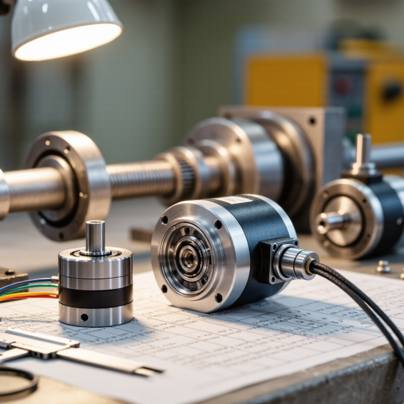
Choosing Rotary Sensors starts with the motion you need to measure. Is the shaft turning slowly or racing through thousands of revolutions per minute? Does the control system need an absolute position, or will incremental pulses do? These details shape the choice more than a product label does. A compact magnetic sensor may tolerate dust and vibration. An optical encoder can offer fine resolution, but its installation and operating conditions matter. Small differences count.
Lord Kelvin, a measurement pioneer, wrote, “When you can measure what you are speaking about, and express it in numbers, you know something about it.” That principle fits sensor selection: define the required resolution, accuracy, speed, and electrical interface before comparing models. Then check the shaft size, mounting space, temperature range, and exposure to moisture or debris. A specification sheet helps, but it cannot replace testing in the actual machine. That part is easy to overlook.
This guide outlines how to match sensor type and performance to an application, assess installation constraints, and compare key specifications. It also considers common trade-offs, including cost, durability, and signal quality. No single design suits every rotary system. A choice that looks clear on paper may need revision after a real installation. That is worth admitting. A careful selection process can reduce integration surprises and support dependable position or speed feedback.
Identify the Measurement Requirements and Operating Range
Begin with the movement itself: Does the shaft turn continuously, reverse direction, or stop at fixed angles? Record its full travel, maximum speed, acceleration, and required resolution. A valve moving through 90 degrees needs a different range from a motor shaft making thousands of revolutions per minute. Check the real operating limits, not just the machine’s normal cycle. Startup surges and mechanical play can matter.
Define the measurement tolerance before comparing sensor specifications. If a control system allows 0.5 degrees of total position error, reserve only part of that budget for the sensor; mounting alignment and signal processing add errors too. NIST Technical Note 1297 describes expanded uncertainty as U = kuc; with a coverage factor of 2, it often represents about 95% coverage under stated assumptions. That is a useful reminder: a quoted accuracy number is not the whole measurement story. Ask whether it applies across the full temperature and speed range.
Then inspect the installation. Note available shaft space, vibration, dust, moisture, and nearby electrical noise. A sensor that meets the angle requirement on a clean test bench may drift in a hot, vibrating enclosure. I have seen specifications chosen too narrowly around steady-state speed. Leave operating margin, but do not overbuy resolution you cannot use. Recheck the assumptions against actual machine behavior.
How to Choose Rotary Sensors: Measurement Range
Start by identifying the full angular travel your application must measure. These illustrative examples show why checking a sensor’s specified mechanical and measurement range matters: actual limits vary by model.
A rotary potentiometer with 300° of travel covers about 0.83 revolution; a single-turn absolute encoder covers one revolution; and a multi-turn absolute encoder with a 12-bit turn counter can represent 4,096 revolutions. Confirm travel limits, resolution, and environmental ratings in the sensor datasheet before selecting a device.
Compare Rotary Sensor Technologies and Their Operating Principles
Rotary sensors turn shaft movement into electrical signals, but their operating principles determine what they measure well. Optical encoders read patterned disks with light, offering fine position steps. Dust, oil, or a misaligned disk can disrupt the reading. Magnetic sensors detect changes in a rotating magnetic field; they tolerate grime and vibration better, though nearby magnetic fields may affect results. Resolvers use electromagnetic coupling to produce sine and cosine signals. They suit hot, harsh environments, but need more involved signal conversion.
Resolution is not accuracy. That distinction matters. A high pulse count cannot correct shaft runout, mounting error, or temperature drift. For a slow valve, a rugged magnetic sensor may be more useful than a very fine optical unit. A servo axis needing precise position feedback may favor an optical encoder, while a motor in a hot enclosure may call for a resolver. Check the full operating range, not just the headline resolution.
The International Federation of Robotics’ World Robotics 2023 report recorded 553,052 industrial robot installations worldwide in 2022, 5% more than in 2021. That growth makes reliable motion feedback increasingly important, but it does not point to one universal sensor. Compare accuracy, repeatability, speed, temperature limits, contamination exposure, and interface needs against the actual shaft and installation. I would still test the chosen sensor on the real assembly: catalog conditions rarely capture every vibration, cable run, or alignment imperfection.
Evaluate Accuracy, Resolution, Linearity, and Response Speed
Choosing a rotary sensor starts with the motion it must measure. For a robotic joint, small angular errors can shift a tool tip; on a conveyor, repeatable speed readings may matter. Accuracy describes closeness to the true angle, while resolution describes the smallest detectable change. More counts do not guarantee greater accuracy. Check linearity across the full rotation, not just at one convenient point. NIST Technical Note 1297 explains that expanded measurement uncertainty is calculated from combined uncertainty; a coverage factor of 2 corresponds to roughly 95% coverage under stated distribution assumptions. That is a useful reminder: a precise-looking number still has uncertainty.
Response speed matters when motion changes quickly. Compare sensor bandwidth and latency with the machine’s fastest expected movement, then check whether the controller samples fast enough. ISO 230-2:2014 provides methods for testing positioning accuracy and repeatability of numerically controlled machine axes; its test approach can help assess rotary stages, though it does not replace the sensor’s own specifications. Ask for test conditions, including temperature and rotation speed. I still find this easy to overlook: a clean datasheet may hide performance limits outside its test setup. A practical trial under real operating conditions can expose them.
Check Environmental Conditions, Mounting, and Electrical Compatibility
Choose environmental limits from the actual installation, not just nominal room conditions. Heat near a motor, condensation inside an enclosure, oil mist, dust, and vibration can all affect sensor life. Check the specified operating temperature, ingress protection, shock, and vibration ratings against the worst conditions expected. Leave margin; machines rarely behave exactly like the test bench. Small details matter.
Mounting geometry deserves equal attention. Confirm shaft diameter, allowable radial and axial loads, rotation range, and available clearance before ordering. A bracket that flexes or a misaligned coupling can introduce error and shorten bearing life. It is tempting to treat the datasheet as the whole answer, but that assumption is often too neat.
For electrical compatibility, match supply voltage, output type, signal level, connector, and cable length to the controller. Check whether the input expects an analog voltage, current loop, incremental pulses, or an absolute digital protocol. Verify resolution and update rate, too; more counts do not help if the controller cannot read them reliably. Grounding, shielding, and nearby drives can affect signal quality, especially over long cable runs. Measure twice. Before installation, compare the wiring diagram with the actual input terminals and test the signal at operating speed.
Review Calibration, Reliability, and Long-Term Maintenance Needs
A rotary sensor should match the movement, environment, and accuracy your application actually requires. Check its measurement range, resolution, and operating speed against real machine conditions, not just ideal specifications. Calibration needs deserve equal attention. Ask how the sensor is calibrated, what reference equipment is needed, and how often readings should be checked. A small zero-point shift can affect a positioning task. Small errors matter.
Reliability depends on more than a sealed housing. Vibration, temperature changes, dust, and repeated rotation can all influence performance. Review the expected service life and the conditions behind any published ratings. Plan long-term maintenance before installation: access to connectors, replacement time, and availability of calibration support can affect downtime. A detail teams sometimes miss is cable routing; repeated flexing may cause trouble even when the sensor itself remains sound. It is worth revisiting assumptions after the first weeks of operation.
Tips
Keep a simple log of calibration dates, readings, and environmental changes. Compare measurements at the same shaft position, using a stable reference. If readings drift, inspect mounting and wiring before changing settings. Record what you find. This routine will not catch every fault, but it can reveal gradual changes early.
