Choosing a High Torque Brushless Dc Motor in 2026 means matching the motor to the work, not simply choosing the largest torque rating. A conveyor starting with a full load has different needs from a compact robot arm that changes direction often. Begin with required torque, operating speed, supply voltage, and available space. Then consider how long the motor must run and how often it starts or stops. These details shape current demand and heat buildup. Heat matters. A motor that performs well for a brief test may struggle during a long shift. Check the manufacturer’s torque-speed curve, rated current, thermal limits, and mounting dimensions. If a gearbox is needed, include its efficiency and backlash in the selection.
Control compatibility deserves equal attention. Confirm that the motor works with the intended drive, feedback device, and control method. A precise encoder may help with positioning, while a simpler setup may suit steady-speed operation. In 2026, product pages and selection tools can make comparisons faster, but they do not replace a careful review of the datasheet. Look for clear test conditions and consistent units. A tidy spreadsheet can still hide an important mismatch. It is easy to overlook peak torque duration or cooling requirements. Ask the supplier about these points, then test the motor under realistic load before committing to a production design. No single specification tells the whole story. The best choice balances performance, reliability, installation constraints, and service needs.
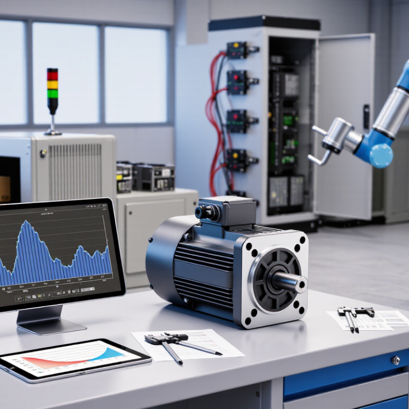
Start with the load, not the catalog. Record the torque needed to start, accelerate, hold, and stop the mechanism. Peak torque matters. A conveyor may need extra torque when fully loaded, while a robotic joint faces brief acceleration spikes. Include friction, gearing, and reflected inertia; ignoring them can leave the motor undersized. Then match torque to speed across the full operating range. A motor’s maximum torque at low speed does not guarantee the same output at the required running speed. Check its torque-speed curve, and calculate mechanical power using torque and angular speed.
Describe the real duty cycle: operating time, rest periods, starts per hour, and any stalls or reversals. Heat is unforgiving. Continuous torque ratings assume specific cooling and ambient conditions, so a compact motor inside a warm enclosure may need derating.
The U.S. Department of Energy’s 2014 United States Industrial Electric Motor Systems Market Assessment estimated that motor-driven systems accounted for 68% of U.S. manufacturing electricity use.
That figure covers industrial motor systems broadly, not brushless motors alone, but it shows why operating conditions matter. I still allow a measured margin for load variation, then verify temperatures and performance under the actual cycle. Too much margin can also mean unnecessary size and cost.
Compare motor types, ratings, and performance curves before choosing a motor. A high peak-torque figure alone can mislead. Check whether the curve shows continuous torque, peak torque, or both. Continuous torque is the key figure for sustained loads; peak torque usually applies only briefly. An outer-rotor design can provide strong torque at lower speeds, while an inner-rotor motor often suits higher-speed applications, sometimes with gearing. BLDC and PMSM labels can overlap in product literature, so check the commutation method and controller requirements. Details matter.
Read the torque-speed curve at your intended supply voltage. Note how torque falls as speed rises, and check the current and temperature limits. A motor may reach the required torque on a cold test bench but struggle inside a warm, enclosed machine. That assumption can fail. The International Energy Agency’s 2011 report, Energy-Efficiency Policy Opportunities for Electric Motor-Driven Systems, estimates these systems use 43–46% of global electricity. That figure highlights why matching motor and load matters.
Compare rated voltage, current, speed, and duty cycle using consistent conditions. IEC 60034-1 defines rating and performance requirements for rotating electrical machines, including duty classifications. Look for an S1 continuous-duty rating when the load runs steadily, and confirm cooling and mounting conditions match your installation. Curves are useful, not perfect: ask how measurements were taken and whether the controller was included. A small mismatch can change the result.
How to Choose a High Torque Brushless DC Motor in 2026?
Match the Motor to Its Controller and Mechanical Load
A high-torque motor is only useful when its controller and load agree. Start with the load’s torque-speed curve, not its peak-torque headline. A conveyor may need steady torque at low speed; a robotic joint may need brief acceleration peaks. Record continuous torque, peak torque, speed, duty cycle, and reflected inertia. Then compare those values with the motor’s torque-speed curve. The U.S. Department of Energy’s 2014 motor systems sourcebook estimates that motor-driven systems account for about 68% of U.S. manufacturing electricity use. That figure covers many motor types, but it shows why poor matching can waste energy.
Check controller phase-current limits against the motor’s continuous and peak ratings. Confirm that supply voltage leaves enough speed headroom as back-EMF rises. Also check commutation support, feedback sensors, and current limits during acceleration. A gearbox can increase output torque, but it adds losses and may change the load’s reflected inertia. The IEA’s 2011 analysis estimated that electric motor systems use about 45% of global electricity. Its estimate is broad, not specific to brushless DC motors. Still, efficiency deserves attention. A selection can look right on paper and run hot in a real enclosure. I would test the actual load across its full duty cycle, then revisit the current and thermal margins. That step is easy to underestimate.
How to Choose a High Torque Brushless DC Motor in 2026?
A high torque figure means little if the motor overheats during the real duty cycle. Check continuous torque, peak torque, and how long each peak lasts. Low-speed operation can reduce airflow in fan-cooled designs, while repeated starts add heat. Leave thermal margin. I still treat neat spreadsheet estimates as optimistic; a sealed housing can change the result.
The International Energy Agency’s 2011 report, Energy-Efficiency Policy Opportunities for Electric Motor-Driven Systems, estimates that motor-driven systems use about 45% of global electricity. That scale makes efficiency and heat management practical concerns, not minor details. IEC 60085 assigns thermal classes F and H ratings of 155°C and 180°C, respectively. These are insulation-system limits, not recommended winding temperatures for every motor.
Match the frame size to the available mounting space, but also allow room for heat to escape. Measure clearance around the motor and note nearby warm surfaces, dust, moisture, vibration, and altitude. Then check the specified ambient temperature and protection rating against the actual installation. A compact motor may fit perfectly and still struggle in a hot, enclosed cabinet. Small mismatch, big consequence. Ask for test data at your intended speed, load, and cooling conditions; catalog torque alone cannot predict site performance.
Compare continuous and peak torque across representative motor frame sizes.
These illustrative values show how torque capacity generally increases with motor size; they are not specifications for a particular motor. Choose a motor whose continuous torque meets the sustained load, and treat peak torque as short-duration capacity. Check winding and case temperature limits, cooling, duty cycle, and ambient temperature: operation in hot or confined environments can require thermal derating. Confirm final ratings with the motor’s datasheet.
How to Choose a High Torque Brushless DC Motor in 2026?
High torque matters most when a motor starts under load, not just when its shaft spins freely. Check continuous torque, peak torque, speed, and the duration allowed at peak load. Then match these figures to your real duty cycle, including frequent starts or a warm enclosure. The IEA’s Energy Efficiency 2023 report notes that motor-driven systems use more than 40% of global electricity. Small efficiency differences can therefore matter across long operating hours. Ask suppliers for efficiency curves across your working speed and load range, not only a single peak figure. A glossy peak-efficiency number can mislead.
Reliability depends on more than the motor’s rated life. Request winding temperature limits, bearing details, insulation class, thermal protection, and test conditions. Confirm that torque and efficiency figures use a recognized method, such as IEC 60034-2-1, and ask for a test report tied to the offered motor configuration. Verify voltage, controller compatibility, shaft dimensions, and the meaning of each rating. If the supplier cannot explain a specification clearly, pause. I have seen a promising rating become less useful once the application’s low-speed heating was considered.
Tips: Ask for a sample test report. Compare continuous torque at your actual operating speed. Confirm the supplier’s production tolerances and traceability. Check what happens when a unit fails. A lower price may still cost more in downtime.
| Selection Dimension | What to Verify | Practical Check or Calculation | Evidence to Request |
|---|---|---|---|
| Required continuous torque | Torque needed throughout normal operation, including the load, friction, and any transmission losses. | Calculate from the application load. For rotary power, use T (N·m) = 9550 × P (kW) ÷ n (rpm). For example, 1 kW at 3,000 rpm corresponds to approximately 3.18 N·m. | Application duty profile, load calculations, and the motor’s continuous torque-speed curve. |
| Peak and starting torque | Short-duration torque for acceleration, breakaway, or temporary load increases—and the permitted duration. | Compare required peak torque with the manufacturer’s peak rating and its time limit. Do not treat peak torque as a continuous rating. | Peak torque specification, overload duration, repetition limits, and controller current limits. |
| Speed and operating point | Required minimum, nominal, and maximum speed; confirm torque is available at each operating point. | Check the full torque-speed curve at the actual supply voltage and controller settings. A maximum no-load speed alone does not confirm usable loaded performance. | Torque-speed curves, test conditions, winding configuration, and operating-voltage range. |
| Efficiency and heat | Motor efficiency at the application’s real speed and load, not just a best-case peak figure. | Efficiency is mechanical output power divided by electrical input power. At 1 kW output and 90% efficiency, input power is about 1.11 kW and losses are about 0.11 kW. | Efficiency map or test report identifying the measurement method, operating point, voltage, and temperature. For applicable rotating electrical machines, ask whether testing follows IEC 60034-2-1. |
| Thermal capability | Winding temperature under the intended duty cycle, ambient temperature, cooling method, and mounting arrangement. | Confirm that continuous torque is rated for the actual installation. Enclosure, airflow, mounting, and repeated acceleration can change thermal performance. | Thermal limits, temperature-rise data, duty rating, insulation information, and any required cooling conditions. |
| Duty cycle | Whether operation is continuous, intermittent, reversing, or characterized by frequent starts and stops. | Provide a time-based load and speed profile. Average load alone may conceal demanding starts, braking, or short overloads. | Duty-cycle definition and test results that match the stated operating profile. |
| Electrical compatibility | DC bus voltage, phase current, controller compatibility, back-EMF, and sensor or commutation requirements. | Check both continuous and peak current against the motor and controller ratings. Verify that supply voltage remains within limits during acceleration and regeneration. | Winding data, current ratings, back-EMF constant, wiring diagram, and encoder or Hall-sensor specifications where applicable. |
| Mechanical fit and shaft load | Frame dimensions, shaft and key details, mounting pattern, allowable radial and axial loads, and rotor inertia. | Compare the complete mechanical drawing with the installation. Account for belt tension, coupling forces, and load-induced bearing stress. | Dimensioned drawings, shaft tolerances, bearing information, and allowable-load data. |
| Environmental protection | Exposure to dust, water, vibration, chemicals, and ambient-temperature extremes. | Select an enclosure rating that matches the installation; an IP code describes specified ingress protection, not general resistance to every environment. | Declared IP rating and test documentation. IEC 60529 is the reference standard for IP-code classification. |
| Reliability and service life | Bearing life assumptions, insulation limits, maintenance needs, and performance under the application’s real loads. | Request the assumptions behind any life estimate; service life depends on load, speed, temperature, lubrication, alignment, and operating conditions. | Reliability or endurance test reports, bearing-life calculation basis, maintenance guidance, and warranty terms. |
| Supplier specification quality | Whether ratings are complete, traceable, and stated under clearly defined test conditions. | Check that continuous and peak values are distinguished and that voltage, speed, cooling, ambient temperature, and duty conditions are specified. | Controlled datasheet, test methods, inspection records, change-control process, and written confirmation of deviations. |
| Final selection decision | Fit across torque, speed, efficiency, thermal, electrical, mechanical, and environmental requirements. | Compare candidate motors against the same application profile and verify the intended operating points before approval. | Application-specific sizing review and, where practical, a prototype test under representative load and environmental conditions. |
Note: The numerical example is a calculation, not a product rating. Motor ratings and test results vary by design and operating conditions; confirm all specifications with the supplier.
MSIRobot