Icon about-block-ico-1 Icon about-block-ico-2 Icon about-block-ico-3 Icon about-block-ico-4 Icon announcement-close Icon arrow-left Icon arrow-right Icon arrow-sm Icon asterisk Icon banner-transparent-vector Icon btn-callback-ico Icon careers-item-location Icon careers-item-time Icon careers-item-type Icon careers-mail-ico Icon careers-phone-ico Icon careers-search-ico Icon careers-single-hero-vector Icon careers-single-more-vector Icon careers-vector Icon check Icon close Icon dfm-image-left-vector Icon dfm-image-right-vector Icon document Icon download-popup-vector Icon dropdown Icon envelope Icon facebook Icon faq-banner-bg Icon faq-title-ico-active Icon faq-title-ico Icon featured-links-block-bg Icon figure-1 Icon figure-10 Icon figure-11 Icon figure-12 Icon figure-13 Icon figure-14 Icon figure-15 Icon figure-2 Icon figure-3 Icon figure-4 Icon figure-5 Icon figure-6 Icon figure-7 Icon figure-8 Icon figure-9 Icon file-upload Icon form-sidebar-back Icon form-step-done Icon gmap-marker-group-icon Icon gmap-marker-icon Icon header-profile-ico Icon instagram Icon link Icon linkedin Icon loader Icon mail Icon phone Icon play-yt Icon play Icon post-nav-arr-left Icon quote-banner-vector Icon quote-block-aside-vector Icon quote-contact-phone-ico Icon quote-contact-position-ico Icon sidebar-location Icon sidebar-phone Icon technology-banner-nav-left-vector Icon technology-banner-nav-right-vector Icon twitter Icon webinar-item-date-vector Icon whitepaper-img-ico-left Icon whitepaper-img-ico-right Icon whitepapers-listing-banner-ico Icon whitepapers-single-aside-vector Icon youtube Icon yt-play-button

How to Choose a Single Cartridge Mechanical Seal

Choosing a Single Cartridge Mechanical Seal is not simply a matter of matching shaft size. The seal must suit the pump, fluid, operating conditions, and maintenance plan. A model that performs well with clean water may struggle with abrasive slurry or hot process fluid. Details matter. Check the equipment drawing, seal chamber dimensions, shaft runout, and available installation space before comparing options. Consider pressure, temperature, speed, and whether the pump may run dry during startup. Even a brief dry run can damage seal faces.

Single cartridge designs arrive preassembled, which can reduce installation errors and simplify replacement. But “preassembled” does not mean “fits every pump.” Confirm compatibility for the seal faces, elastomers, and metal parts, including exposure to cleaning chemicals. Request the manufacturer’s operating limits and installation instructions, then compare them with the pump’s nameplate and service history. If operating conditions vary, record both normal and worst-case values. An average alone can hide the real risk. One detail is often missed.

This guide explains how to assess materials, dimensions, operating limits, and support before selecting a seal. It also considers the practical cost of installation and maintenance, not just the initial purchase price. Ask focused questions, verify specifications, and involve a qualified pump or seal specialist when data is incomplete. That extra check may feel slow. It is usually cheaper than an early failure, an unplanned shutdown, or repeated leakage. No catalog can replace accurate site information.
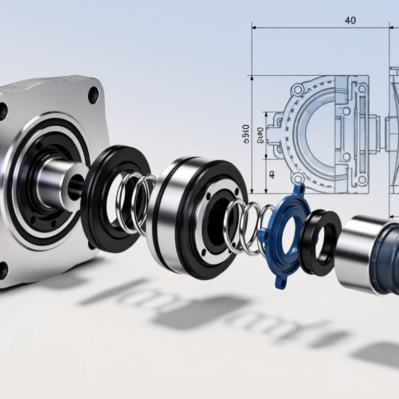
How to Choose a Single Cartridge Mechanical Seal

Identify Arrangement 1 within API 682’s three mechanical-seal arrangements

API 682 divides mechanical seals into three arrangements: Arrangement 1 is a single seal; Arrangements 2 and 3 use dual seals. “Cartridge” describes how the seal is assembled and installed, not its API arrangement. A cartridge seal can therefore belong to different arrangements. Check the equipment datasheet and seal drawing before selecting one. Look for the process fluid, operating pressure, temperature, and specified piping plan. Small details matter.

Arrangement 1 may suit services where a single seal provides acceptable containment and the process fluid supports reliable face lubrication. It does not automatically suit every pump or fluid. Consider vapor pressure, solids, seal-chamber conditions, and the consequences of leakage. The U.S. Department of Energy’s 2006 Improving Pumping System Performance sourcebook reports that pumping systems can use 25–50% of energy in some industrial facilities. That figure concerns whole pumping systems, not seals, but it underscores why operating conditions and maintenance deserve attention. Keep it in perspective. A rushed selection can overlook flush requirements or poor heat removal. Compare the actual service conditions with API 682 requirements, then confirm the arrangement and support plan with qualified engineering personnel.

How to Choose a Single Cartridge Mechanical Seal

Identify Arrangement 1 within API 682’s three mechanical-seal arrangements

Arrangement 1 is the single-seal arrangement. Arrangements 2 and 3 use dual seals: Arrangement 2 has an unpressurized buffer fluid between the seals, while Arrangement 3 has a pressurized barrier fluid. The bars show the number of mechanical seals in each arrangement.

Compare operating pressure, temperature, and speed with the seal’s rated limits

How to Choose a Single Cartridge Mechanical Seal

Compare the pump’s real operating conditions with the seal’s rated limits, not just its nameplate figures. Check differential pressure across the seal faces, process temperature, and shaft speed. These values interact. A seal rated for a certain pressure may not tolerate that pressure at maximum speed and temperature.

Allow for the full operating range. Startup can bring brief pressure changes, while a hot flush may raise the seal-chamber temperature above the normal process reading. Note the fluid’s properties and any solids that could affect face lubrication. Small details matter. If the equipment runs near a stated limit, ask the seal supplier to confirm the combined operating envelope for the selected materials and configuration.

Use measured plant data where possible, and include expected upset conditions. Discharge pressure alone can be misleading; the relevant figure is the pressure difference across the seal. Check speed at the actual drive setting, including any variable-speed operation. I have seen selection sheets omit short startup periods. That gap deserves a second look. Leave operating margin rather than treating the maximum rating as a routine target, and verify that the seal-chamber temperature reflects the installed arrangement.

Match face materials and elastomers to fluid chemistry and solids content

A single-cartridge seal should be selected around the actual fluid, not its generic name. Check concentration, temperature, pH, and cleaning chemicals; a dilute process stream can become aggressive during washdown. For seal faces, carbon often suits clean, lubricating liquids, while silicon carbide handles many abrasive or corrosive duties. No material is universal. Fine solids can still score faces, especially when flushing is poor.

Elastomers need the same scrutiny. EPDM is commonly considered for water and steam, while FKM is often used with oils and hydrocarbons; confirm compatibility at operating temperature. The U.S. Department of Energy’s Improving Pumping System Performance sourcebook estimates pumping systems use nearly 20% of global electricity, underscoring the cost of poor reliability. Seal failures add maintenance and downtime. Ask for immersion or compatibility data for the exact fluid blend, then check hardness, swelling, and temperature limits. A catalog chart is only a starting point. I would also review particle size and concentration: “solids present” is not a useful specification by itself. The final choice may still need a controlled trial.

Select an API piping plan, such as Plan 11, to suit the flush requirements

A single cartridge mechanical seal simplifies installation, but its piping plan still needs careful selection. API Plan 11 routes clean process fluid from the pump discharge through an orifice into the seal chamber. It can provide circulation and help remove heat when the fluid is compatible with the seal faces and contains few solids. Check the fluid’s temperature, vapor pressure, and tendency to crystallize before choosing it. A small orifice can clog. That detail is easy to miss.

Plan 11 is not a universal answer. For a hot or dirty process, recirculating discharge fluid may add heat or carry particles toward the seal. Review the pump’s operating range and the seal chamber’s pressure and temperature, then confirm the plan against API 682 and the equipment supplier’s data. The U.S. Department of Energy’s Improving Pumping System Performance sourcebook reports that pumping systems account for nearly 20% of global electricity demand, and 25–50% of energy use in some industrial operations. Those figures concern whole pumping systems, not seal plans specifically, but they underline why sound pump and seal decisions matter. I still find it tempting to default to Plan 11; process conditions should decide instead.

Verify cartridge dimensions and documentation against API 682 requirements

A single cartridge seal should match the pump, not just the shaft diameter. Compare the seal drawing with the pump’s chamber drawing and the applicable API 682 edition. Check shaft size, chamber bore and depth, gland register, bolt pattern, and available axial space. Small gaps matter. A register that looks close on paper may still prevent the gland from seating flat.

Use a depth gauge and calipers to confirm critical dimensions where access allows. Record the measurements; do not rely only on an old pump manual. Check the cartridge’s setting length, sleeve fit, and installation clearances against the drawing. Confirm that the seal type, arrangement, and category match the project specification. Even a neat drawing can hide an assumption, especially when pump modifications were made after the original records were issued.

Review the documentation before accepting the seal. Request a completed API 682 data sheet and drawings that identify materials, operating limits, and any specified seal support plan. Compare pressure and temperature limits with the actual service conditions, including startup. Check installation instructions and the inspection or test records required by the purchase specification. If a dimension or document conflicts, pause and resolve it with the pump and seal suppliers before installation. Guessing is tempting. It can turn a simple fit-up into rework.

How to Choose a Single Cartridge Mechanical Seal - Verify cartridge dimensions and documentation against API 682 requirements

Use the project-specified edition of API 682 and the pump's approved drawings as the governing references. The example measurements below are illustrative checks, not universal API 682 dimensions; confirm all interfaces and limits for the specific pump and seal arrangement.

Verification item What to verify Illustrative record Acceptance check
Applicable standard Confirm the API 682 edition, seal category, arrangement, and qualification requirements specified in the purchase documents. Project specifies API 682, 4th Edition; single seal, Arrangement 1. Seal datasheet and vendor documentation identify the same specified edition and configuration. Do not assume an edition or arrangement that is not stated in the project documents.
Seal type and cartridge construction Check that the assembly is supplied as a single cartridge seal and that its configuration matches the required arrangement and process service. Single cartridge assembly; one seal set; process-side seal faces identified on the drawing. Confirm the assembly description, sectional drawing, and datasheet agree. Verify any required containment or external support system separately.
Shaft or sleeve diameter Measure the pump shaft or existing sleeve at the seal mounting location and compare it with the cartridge bore and approved pump drawing. Pump sleeve: 50.00 mm nominal; cartridge bore: 50.00 mm nominal. Confirm the specified fit, tolerances, surface condition, and any sleeve requirements on the approved drawings. Nominal values alone do not establish an acceptable fit.
Seal chamber bore Check the seal chamber inside diameter and verify radial clearance for the cartridge components, including any centering or restriction features. Measured chamber bore: 100.0 mm; cartridge outside envelope shown on drawing: 96.0 mm. Compare measured dimensions and allowable clearances with the pump drawing and seal manufacturer's installation drawing. Confirm there is no interference throughout the assembly.
Chamber depth and seal setting Verify the distance from the chamber face to the relevant internal shoulder or seal-seat location, and confirm the cartridge's setting dimension. Chamber depth on pump drawing: 45 mm; cartridge setting dimension on installation drawing: 32 mm. Use the drawing's stated datums and tolerances. Confirm the cartridge can reach its specified installed position without bottoming out or compromising the seal setting.
Gland dimensions and mounting Compare the gland outside diameter, pilot or register, bolt pattern, bolt-hole size, and gasket interface with the pump seal chamber. Gland register: 120 mm; four mounting holes: 14 mm diameter on a 150 mm bolt circle. These are example values only. Verify the actual register, hole count, hole sizes, bolt circle, and gasket dimensions against the pump drawing; confirm the gland seats flat and concentric.
Axial and radial clearances Check available space around the cartridge and rotating parts, including clearance to the shaft, sleeve, chamber, and adjacent pump components. Drawing review records 2.0 mm nominal radial clearance at the identified cartridge envelope. Verify the minimum clearance at worst-case tolerances and consider shaft movement, runout, and thermal effects as required by the project design.
Connections and orientation Identify required flush, drain, vent, quench, or other connections and verify port size, thread or flange type, location, and orientation. One 1/2 in NPT flush connection; port orientation shown at the top of the gland in the installation drawing. Match the project piping plan and seal support-system requirements. Confirm that ports are accessible and that venting and drainage are practical for the installation.
Materials and process limits Review face, elastomer, spring, and metal materials against the process fluid, operating temperature, pressure, and corrosion conditions. Face pairing, elastomer designation, and wetted-metal grade listed on the seal datasheet; design limits stated separately. Check material compatibility and stated operating limits against the process datasheet and project requirements. Do not infer suitability from a generic material description.
Seal datasheet and drawings Obtain the completed seal datasheet, dimensional installation drawing, sectional drawing, and interface details. Document register lists a datasheet, general arrangement drawing, sectional drawing, and installation instructions. Ensure documents are revision-controlled and approved for the exact pump model, seal configuration, and supplied cartridge.
Setting devices and installation instructions Confirm setting clips, spacers, or other shipment and installation devices are identified, with instructions for when to remove them. Setting clips shown in the drawing; removal step included in the installation procedure. Verify the documented setting method and installation sequence. Do not remove setting devices until the specified installation step.
Testing and quality records Review the required inspection, test, material, and traceability records specified by the purchase order and applicable API 682 provisions. Inspection and test plan identifies required checks; material certificates and final inspection records listed for submission. Confirm the records meet the contract and project quality requirements. Test scope and acceptance criteria should be taken from the applicable standard and purchase documents.
Final fit-up confirmation Record measured pump interfaces and compare them with the approved seal drawing before installation. Checklist records shaft/sleeve diameter, chamber bore and depth, gland register, bolt pattern, and port orientation. Resolve any mismatch with the responsible engineering parties before installation; do not modify the cartridge or pump interfaces without approved instructions.

MSIRobot