
How to Choose the Best Steel Cable Tray for Your Project
Choosing the best Steel Cable Tray begins with the installation environment, not the catalogue photograph. Outdoor rooftops, chemical rooms, tunnels, and data centers demand different protection. A tray that looks strong may still fail under corrosion, concentrated loading, poor support spacing, or water accumulation. Small details matter.
IEC 61537:2023 evaluates cable tray and cable ladder systems, including mechanical performance, corrosion protection, and electrical continuity. NEMA VE 1-2023 provides widely used requirements for metallic cable tray construction and testing. NFPA 70, the National Electrical Code, also addresses cable-tray installation, conductor fill, grounding, and support practices. These documents do not replace engineering judgment. They make weak assumptions easier to find.
Mark Earley, a respected electrical safety specialist and former NFPA technical authority, has emphasized, “Installation conditions matter as much as the product rating.” That warning deserves attention. A galvanized Steel Cable Tray may suit a dry warehouse, yet stainless steel could be wiser near salt spray or aggressive chemicals. Aluminum may reduce weight, but it can change bonding and support calculations.
Market research from Grand View Research identifies continued growth in cable-management demand, driven by data centers, renewable energy, and industrial construction. Growth does not make every tray suitable. It increases the cost of choosing poorly. Check span tables, working load, deflection limits, finish thickness, fittings, and grounding continuity before approval. Do not trust a single number. Actual site conditions are often messier than design drawings. That is where careful selection proves its value.
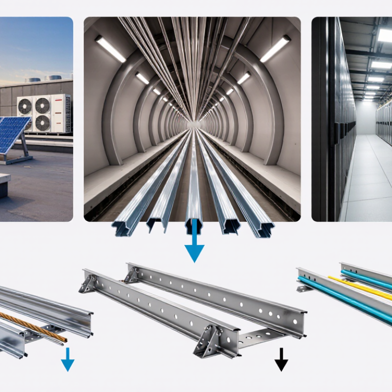
Project Requirements for Steel Cable Tray Selection
How to Choose the Best Steel Cable Tray for Your Project
Project Requirements for Steel Cable Tray Selection
Selecting a steel cable tray begins with the project’s actual operating conditions. Identify cable quantity, total weight, span length, and expected expansion. Measure twice. Allow room for future circuits.
A site review should record ceiling height, access routes, moisture, dust, chemicals, and temperature changes. Indoor office areas may need a different finish than coastal or industrial locations. Choose tray width and depth according to cable fill requirements, bend radius, and maintenance access. Overcrowding can restrict airflow and make later inspection difficult.
Structural performance deserves careful attention. Confirm the tray’s load rating at the planned support spacing, not only its maximum published capacity. Check connection strength, deflection limits, grounding continuity, and compatibility with supports. Hot-dip galvanized steel can suit many demanding environments, while specialized protective finishes may be necessary under severe exposure. Verify these choices against applicable electrical and construction codes.
During installation, inspect cut edges, fasteners, splice plates, and bonding points. Sharp edges can damage insulation. I have seen small alignment errors create problems at turns and vertical drops. A simple mock-up often reveals them early. It is not always practical, and teams sometimes skip it, but that decision deserves review. Keep clear separation from heat sources and water lines. Document tray routes, support locations, and any field changes for future technicians.
How to Choose the Best Steel Cable Tray for Your Project - Project Requirements for Steel Cable Tray Selection
| Project Requirement | Information to Define | Recommended Selection Guidance | Typical Design Values or Options | Verification Before Purchase |
|---|---|---|---|---|
| Cable Type and Quantity | Cable insulation, outside diameter, quantity, weight, voltage level, and whether power and communication cables share the route. | Select a tray with sufficient usable width and separation features for the cable arrangement. Keep power, control, and data cables separated when required by the design or applicable code. | Power cables Control cables Data cables Cable quantity and outside diameter should be based on the actual cable schedule, not nominal cable size. | Prepare a cable schedule, calculate the total cable cross-sectional area, and confirm the required segregation method with the electrical engineer. |
| Required Tray Width | Total cable occupancy, future expansion allowance, and the arrangement of single-layer or multi-layer cables. | Choose the next available tray width above the calculated requirement. Avoid filling the tray to its physical edge because installation, heat dissipation, and future maintenance require working space. | Common nominal widths include 150, 300, 450, 600, 750, and 900 mm. The final width depends on the cable layout and applicable fill limits. | Calculate the usable internal width, confirm the manufacturer’s fill recommendation, and include a documented spare-capacity allowance where required. |
| Load Capacity | Cable weight per metre, tray self-weight, covers, accessories, ice or dust accumulation, and any external loads. | The selected tray must have a published load rating greater than the calculated service load. Use the load rating for the actual support span and installation orientation. | Service load is commonly expressed as kg/m or N/m. A typical industrial design may use approximately 75–150 kg/m, but the project calculation controls. | Compare the calculated load with the tested load table for the exact tray width, material, side-rail height, and support span. |
| Support Span | Distance between brackets or hangers, structural layout, access restrictions, and seismic requirements. | Shorter spans generally increase load capacity and reduce deflection. Do not use a load rating from a longer or shorter span without confirming its applicability. | Common support spacing is approximately 1.5–3.0 m. Heavy-duty or seismic installations may require closer spacing. | Coordinate tray supports with the building structure and verify allowable deflection, connection strength, and seismic bracing requirements. |
| Tray Configuration | Cable access, cable type, ventilation needs, route geometry, and the number of bends, tees, and risers. | Use ladder tray for high ventilation and easy cable access, perforated or ventilated tray for general-purpose routing, and solid-bottom tray where additional cable support or protection is needed. | Ladder tray Perforated tray Solid-bottom tray Select fittings with a bend radius suitable for the largest cable. | Review the complete route drawing, including horizontal bends, vertical bends, tees, reducers, drops, covers, and expansion joints. |
| Material and Corrosion Exposure | Indoor or outdoor location, humidity, condensation, salt spray, chemicals, pollution, and washdown conditions. | Choose the steel finish according to the corrosivity of the environment. A protective metallic coating is commonly used for general service, while more robust coatings or stainless steel may be needed for severe exposure. | Pre-galvanized steel Hot-dip galvanized steel Stainless steel Coating selection must match the site environment and expected service life. | Obtain the coating type, coating thickness or mass, salt-spray or corrosion data where relevant, and compatibility information for the installation environment. |
| Temperature and Thermal Management | Ambient temperature, cable operating temperature, solar exposure, heat sources, and cable grouping. | Use a ventilated tray where heat dissipation is important. Confirm the cable ampacity after applying grouping, ambient-temperature, and installation-method correction factors. | Outdoor solar exposure can increase tray and cable temperature. Cable ampacity must be calculated using the applicable electrical standard and actual installation conditions. | Have the electrical designer verify ampacity, cable spacing, ventilation, and any temperature derating before finalizing the tray arrangement. |
| Electrical Bonding and Earthing | Continuity across tray joints, protective bonding, fault-current requirements, and local electrical regulations. | Provide bonding jumpers or approved bonding hardware where required. Tray sections should not be assumed to provide electrical continuity unless the system has been evaluated for that purpose. | Bonding requirements depend on the electrical system, fault level, joint design, and governing code. | Confirm joint resistance, bonding hardware, conductor sizing, and connection to the site earthing system with the responsible electrical engineer. |
| Mechanical Protection | Risk of falling objects, impact, unauthorized access, water entry, dust, and maintenance activities. | Use covers, reinforced side rails, or a more protective tray arrangement where cables are exposed to impact, falling debris, water, or high contamination. | Ventilated cover Solid cover Reinforced tray The protection level should reflect the actual site hazards. | Perform a route hazard review and verify cover fastening, drainage, impact resistance, and access requirements. |
| Fire and Smoke Requirements | Fire compartmentation, fire-rated routes, emergency systems, cable function during fire, and building regulations. | Steel tray is non-combustible, but the complete installation may still require fire stopping, fire-rated supports, protected penetrations, or dedicated fire-survivability systems. | Fire requirements vary by building type, cable function, authority requirements, and project specifications. | Coordinate tray penetrations, fire stopping, support details, and emergency-circuit requirements with the fire-protection and electrical designs. |
| Dimensional Compatibility | Tray width, side-rail height, splice-plate position, fitting geometry, cable bend radius, and available clearance. | Select dimensions that accommodate the largest cable bend radius and maintain clearance from walls, pipes, ducts, doors, and other services. | Common side-rail heights are approximately 50–150 mm. Required bend radius is determined by the cable manufacturer and cable construction. | Overlay the tray route on the coordinated services model and confirm access for cable pulling, inspection, and future replacement. |
| Installation and Maintenance | Site access, lifting limitations, installation tools, cable pulling method, inspection access, and replacement strategy. | Choose manageable section lengths and accessible joint locations. Provide adequate clearance above and beside the tray for pulling, inspection, and maintenance. | Section lengths are commonly selected according to site handling capacity and route conditions rather than a single universal standard. | Review installation sequence, lifting method, joint access, cover removal, cable pulling tension, and planned maintenance procedures. |
| Standards and Testing | Applicable national and project standards, load testing, deflection limits, corrosion documentation, and quality records. | Specify a tray system that has documented performance data for load, deflection, electrical continuity where applicable, and material or coating properties. | Common references may include IEC 61537 or an applicable national equivalent. The project specification and local regulations take precedence. | Request technical drawings, load tables, material certificates, coating records, installation instructions, and test documentation. |
| Future Expansion | Expected additional circuits, spare capacity, future route changes, and plant expansion plans. | Reserve practical capacity without creating excessive cost or unnecessary obstruction. Consider spare width, additional support capacity, and accessible route sections. | A project may reserve approximately 20–30% additional space when permitted by the design basis, although the required allowance is project-specific. | Document the spare-capacity assumption and verify that supports, fittings, and cable separation remain adequate after expansion. |
| Total Installed Cost | Tray sections, fittings, covers, supports, bonding, coatings, transport, installation labor, and maintenance. | Compare complete installed-system cost rather than the price of straight tray sections alone. A durable finish and efficient installation can reduce lifecycle cost. | Cost drivers include material thickness, finish, width, support spacing, fitting quantity, access difficulty, and corrosion exposure. | Request a bill of materials and lifecycle-cost comparison covering tray, fittings, supports, installation, inspection, and replacement requirements. |