Industrial plants depend on motor starters that respond predictably through long shifts, frequent starts, and changing loads. An Ac Magnetic Starter combines a magnetic contactor with overload protection to start and stop a motor. The right choice can help protect equipment and reduce avoidable downtime. A poor match can create heat, nuisance trips, or maintenance headaches.
This guide compares seven AC magnetic starters for industrial use, focusing on practical selection details: motor ratings, coil voltage, overload adjustment, enclosure, and service conditions. A starter beside a dusty conveyor may need different protection from one inside a clean control cabinet. Small details matter. Check the motor nameplate and installation requirements before comparing models; a current rating alone does not tell the whole story.
Motor-drive author Austin Hughes provides relevant technical context, but the following is an editorial paraphrase, not a verbatim quotation: “Select motor-control equipment for the motor’s duty and operating conditions, not its rating alone.” That principle shapes this comparison. It is not a substitute for the manufacturer’s instructions or a qualified review of the installation. And real plants are messy. Even a carefully selected starter can disappoint when wiring, ambient temperature, or maintenance practices are overlooked. This guide aims to make those trade-offs easier to see, while acknowledging that product specifications and availability can change.
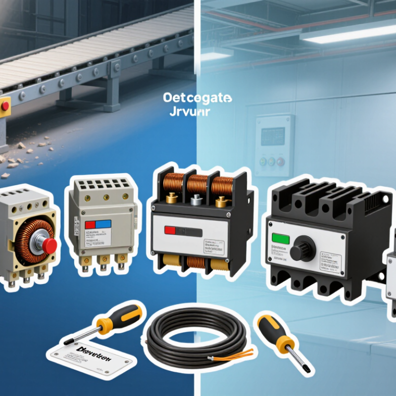
An AC magnetic starter switches an industrial motor through an electromagnetic coil, power contacts, and overload protection. When the control circuit energizes the coil, its magnetic field pulls an armature inward and closes the contacts. The motor receives power. If excessive current persists, the overload relay opens the control circuit and stops the motor. A starter provides switching and protection, but it does not control motor speed. That distinction matters near pumps, conveyors, and fans.
The International Energy Agency’s 2011 report, Energy-Efficiency Policy Opportunities for Electric Motor-Driven Systems, estimates that motor-driven systems use about 46% of global electricity. That figure makes dependable motor operation important, though a starter alone cannot deliver energy savings. Correct selection starts with the motor nameplate current and operating duty. Engineers also consider supply voltage, enclosure conditions, and how often the motor starts. A detail that can be overlooked: frequent starts may create more thermal stress than a simple load estimate suggests.
Tips: Match the overload setting to the motor’s nameplate instructions, and check that the starter’s contact rating suits the application. Confirm the control voltage before wiring. Keep the enclosure clear of dust and heat where practical. Even a correctly sized starter can perform poorly if installation conditions are ignored.
The ranges show typical starting line current as a multiple of motor full-load current (FLA). Actual values vary with motor design, load, equipment settings, and supply conditions. A soft starter’s current limit is adjustable; a VFD typically controls starting current while ramping the motor up to speed.
Choosing an AC magnetic starter means matching it to the motor and its working conditions, not just its horsepower. Check the motor nameplate for voltage, full-load current, phase, and starting method. Confirm the starter’s contactor rating and overload range suit those values. The U.S. Department of Energy’s 2014 motor-systems sourcebook estimates that motor-driven systems account for about 68% of U.S. manufacturing electricity use. That figure makes reliable motor protection important, though a starter alone does not reduce energy consumption.
Tips: Check the required control-coil voltage, operating frequency, and enclosure rating. For dusty or damp areas, the enclosure needs suitable protection. Also verify coordination with the upstream fuse or circuit breaker and available fault current. IEC 60947-4-1 provides requirements for contactors and motor starters; use it alongside equipment ratings and site specifications.
Consider how often the motor starts and stops. Frequent cycling can increase contact wear, while heavy starting loads may require different protection settings. One common oversight is selecting by horsepower alone. I would still check the actual nameplate current and the manufacturer’s coordination tables; assumptions can be wrong. A qualified electrical professional should confirm the final selection and settings before installation.
| Starter Configuration | Typical Industrial Application | Starting Method | Key Advantages | Important Selection Checks |
|---|---|---|---|---|
| Full-Voltage Non-Reversing (FVNR) | General-purpose pumps, fans, compressors, and conveyors that run in one direction. | Connects the motor directly to the supply at start. | Simple control arrangement, direct starting, and widely used for fixed-speed motors. | Check motor full-load current, available supply capacity, starting current, overload range, and whether the driven equipment can tolerate full starting torque. |
| Reversing Magnetic Starter | Reversible conveyors, hoists, machine tools, and other applications requiring forward and reverse operation. | Uses two contactors to change the phase sequence; electrical and mechanical interlocks prevent both contactors from closing together. | Provides controlled direction changes using a contactor-based arrangement. | Verify motor wiring and duty, interlocking, stopping requirements, reversing frequency, overload protection, and the control circuit’s operating logic. |
| Two-Speed Magnetic Starter | Fans, pumps, and processing equipment that need two discrete operating speeds. | Switches the connections of a motor specifically designed for two-speed operation. | Offers two defined speeds without requiring a variable-frequency drive. | Confirm the motor’s two-speed winding arrangement, connection diagram, speed ratio, contactor configuration, and correct overload protection for each operating condition. |
| Wye-Delta (Star-Delta) Starter | Three-phase squirrel-cage motors and loads that can accelerate with reduced starting torque. | Starts the motor in a wye connection, then changes it to delta for normal running. | Reduces starting current compared with direct-on-line starting. | Use only with a motor designed for wye-delta starting and with the required winding terminals available. Check transition timing, load torque, and protection during starting and running. |
| Autotransformer Reduced-Voltage Starter | Large motors where limiting supply-side starting current is important and reduced starting torque is acceptable. | Applies reduced voltage through transformer taps during acceleration, then switches the motor to full voltage. | Provides selectable reduced-voltage starting while allowing the motor to run at full supply voltage. | Confirm motor and load acceleration requirements, tap selection, transition method, transformer rating, starting frequency, and enclosure space. |
| Part-Winding Starter | Motors manufactured with separate winding sections and intended for part-winding starting. | Energizes one part of the winding first, then connects the remaining winding section after a set interval. | Can reduce starting current compared with starting the complete winding at once. | Check that the motor is specifically designed for this method, confirm the correct connection sequence and timing, and assess available starting torque for the driven load. |
| Primary-Resistance Starter | Applications where a simple, staged reduction in motor terminal voltage is suitable. | Places resistors in series with the motor during starting and bypasses them as the motor accelerates. | Provides a straightforward reduced-voltage starting method. | Assess resistor heat dissipation, starting frequency, voltage drop, transition behavior, motor torque, and suitability for the site’s ambient conditions. |
Final selection should be based on the motor nameplate, supply voltage and frequency, full-load current, starting current, load torque, operating duty, required control functions, and installation environment. Confirm the starter and overload protection are rated for the application and applicable electrical codes.
Choosing an AC magnetic starter starts with the motor’s duty, load, and operating environment. The International Energy Agency’s Energy-Efficient Motor Systems report estimates that motor-driven systems consume about 46% of global electricity. That figure describes the wider motor system, not savings from starters alone. Still, it shows why correct motor control matters. Fit matters.
Seven common configurations serve different jobs:
Each requires proper motor and overload coordination. Check the load.
For selection, compare rated voltage, motor current, starts per hour, enclosure conditions, and available fault protection. IEC 60947-4-1 covers contactors and motor starters, including overload protection and coordination requirements. A dusty pump room may need a different enclosure from a clean control cabinet. Starting methods also affect torque, so a reduced-current start may not suit a heavily loaded conveyor. The boundary between a convenient standard configuration and a poor application match is not always obvious; verify the motor data and operating sequence before specifying equipment.
For industrial use, the seven strongest AC magnetic starter choices are not simply the ones with the highest current rating. Compare motor voltage, full-load current, horsepower, and switching duty against the motor nameplate. A starter rated for occasional starts may wear quickly on a conveyor that cycles every few seconds. Fit matters.
Look closely at what each design includes. A basic starter may suit a fixed-speed pump, while a reversing type supports forward and reverse operation. Enclosed models help shield components from dust and accidental contact. Two-speed versions serve motors built for distinct operating speeds. Check the contactor’s utilization rating, too; frequent starting or plugging can create more stress than a light-duty rating suggests. Numbers can mislead.
Protection deserves equal attention. Thermal overload relays help respond to sustained overcurrent, and some units also detect phase loss. Short-circuit protection usually requires a correctly coordinated fuse or circuit breaker; the starter alone may not provide it. Compare reset options, trip adjustment range, enclosure rating, and replacement-part availability. A neat feature list is not proof of a good match. In practice, panel temperature, wiring length, and starting frequency can change performance, so verify the selection against the installation and motor data.
Choose a starter matched to the motor’s voltage, full-load current, duty cycle, and control-circuit supply. Check that the enclosure suits the actual environment: fine dust near a grinder can settle on contacts, while moisture can damage insulation. Confirm short-circuit coordination and set the overload relay to the motor nameplate current, following the equipment instructions. Tighten terminals to specified torque; loose connections can create hot spots. Small details matter.
Plan maintenance around operating conditions, not just the calendar. With power safely isolated, inspect contacts for pitting, check coil connections, and clear dust from ventilation openings. Listen for chatter during operation; it may point to low control voltage, a worn coil, or a poor connection. The U.S. Department of Energy’s 2010 Operations & Maintenance Best Practices Guide reports that predictive maintenance can save 8–12% compared with preventive maintenance. That is a useful benchmark, not a guarantee for every plant. Record inspection findings and recurring faults so intervals can be adjusted.
Tips: Keep a spare coil and contact set on site. After replacement, verify coil voltage and overload settings before returning the starter to service. If a component looks fine, it can still fail under heat; visual checks alone are not enough.
MSIRobot