Aluminium Tri-Fold Blind Rivets For Composite Materials can solve difficult fastening problems in thin, layered structures. Their three expanding legs spread behind the panel, creating a wider bearing area than many conventional blind rivets. This action can reduce pull-through risk in fiberglass, carbon-fiber, and sandwich panels. Small details decide performance.
Composite fastening authority Dr. Stephen W. Tsai is often associated with a valuable design principle: “The load path matters more than the fastener alone.” That idea frames these seven practical tips. Rivet selection should match the laminate thickness, hole diameter, grip range, and expected load direction. Aluminium offers low weight and useful corrosion resistance, but it may not suit every environment or metal combination. Galvanic concerns deserve attention.
Prepare clean, accurately drilled holes. Avoid crushing the laminate during installation. Use washers or backing support when the panel design requires extra load distribution. Check the rivet’s folded legs after setting, not only its visible head. A loose mandrel or uneven expansion may reveal poor installation. It happens.
The best results come from controlled trials using representative coupons. Measure pull-out, shear behavior, hole damage, and surface distortion. Do not trust a catalog value blindly. Real composite panels contain resin variation, voids, coatings, and local curvature. One assumption may fail.
These seven tips focus on practical inspection, material compatibility, installation control, and long-term joint reliability. They are not a substitute for engineering validation. However, they can help technicians and designers make quieter, stronger, and more defensible fastening decisions.
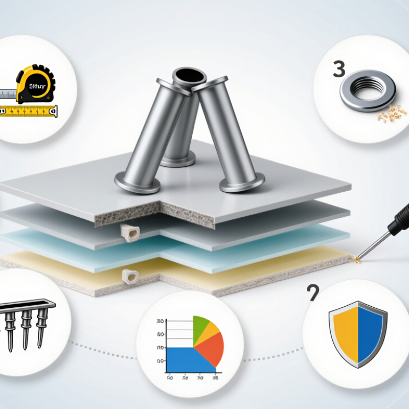
Tip one: match the rivet diameter to the drilled hole, usually from 3.2 to 6.4 mm. A loose hole can reduce load sharing.
Tip two: select a broad, controlled blind-side footprint. Tri-fold legs should spread pressure without crushing the laminate.
Tip three: check the grip range against the total panel thickness, including washers or sealants. Too much excess grip can leave an unstable joint.
Tip four: use a low-profile head where airflow or surface clearance matters. Countersinking composites requires care, because thin skins can lose valuable fibers.
Tip five: choose an aluminium alloy with suitable strength and ductility. Harder alloys may resist deformation, yet softer alloys can form more gently against fragile laminates. The strongest option is not always the safest option.
Tip six: consider galvanic compatibility with nearby fasteners, inserts, and carbon fibers. Isolation layers may be necessary in damp service conditions.
Tip seven: test the selected 3.2, 4.0, 4.8, or 6.4 mm rivet on representative coupons. Measure pull-through, clamp-up, and visible delamination. Real panels often behave differently from drawings.
I have seen a well-sized rivet fail because the hole edge was poorly supported. Inspect the folded legs after installation. They should sit evenly, without sharp laminate distortion or incomplete expansion. Temperature, moisture, and drilling quality can change the result.
7 Tips for Aluminium Tri Fold Blind Rivets in Composites
Grip length controls clamp quality in laminated panels. Measure the complete stack, including skins, core, adhesive, washers, and any surface film. Select a rivet grip that fits this measured thickness, not the nominal drawing value. A rivet that is too short may leave loose plies. One that is too long may form an uneven blind head.
Keep the hole center at least three hole diameters from every free edge. This 3D edge distance reduces splitting and local delamination around the fastener. Mark the distance directly on the panel before drilling. Support the laminate with a backing block, and use a sharp, controlled drill. Avoid forcing the tool through the final ply. Small mistakes grow quickly. Check the hole diameter with a calibrated gauge, not only the drill label.
Dry-fit one rivet from each material stack. Confirm that the mandrel pulls smoothly and the formed head sits squarely. A thin sealant layer may change the effective grip, so include it in the trial measurement. Inspect the entry and blind sides for crushed fibers, lifted plies, or a loose head. If damage appears, pause and review the edge distance, hole quality, and grip selection. Perfect drawings can still mislead when laminate thickness varies across a panel. Record the actual measurements for future assemblies.
7 Tips for Aluminium Tri Fold Blind Rivets in Composites
Hole preparation controls the strength and reliability of a tri fold blind rivet joint. Drill the composite to provide approximately 0.1–0.2 mm clearance around the rivet shank, unless the engineering drawing specifies otherwise. Too little clearance can crush the laminate during installation. Too much clearance may allow movement, uneven folding, and reduced load transfer.
Use a sharp, controlled drill with firm support behind the laminate. Keep the tool aligned with the surface, and avoid forcing it through the final plies. A clean hole should have smooth edges, without lifted fibers or a dark, crushed rim. Inspect both faces under good lighting. Small defects are easy to miss.
Seal exposed fibers before inserting the rivet. Brush away dust, then apply a compatible thin sealant or resin to the hole wall and edge. This barrier helps limit moisture ingress and separates aluminium from conductive carbon fibers. Do not flood the hole; excess material can prevent full rivet expansion. Allow the sealant to reach the required working condition, not necessarily complete hardness, before installation. That detail depends on the product data and assembly schedule.
A practical check is simple. Test one prepared hole first. Measure the rivet fit, inspect the folded legs, and look for laminate compression. I have seen otherwise careful assemblies fail because the sealant was applied after drilling debris remained. That mistake is avoidable, but workshop pressure makes it surprisingly common.
For aluminium tri-fold blind rivets used in composite panels, prepare the hole with approximately 0.1–0.2 mm clearance above the rivet body diameter. The resulting range shown below supports fit-up while limiting unnecessary movement. After drilling, remove debris and seal exposed composite fibers to reduce moisture ingress and fiber damage.
Aluminium tri-fold blind rivets can secure composite panels when installation pressure is carefully controlled. Their three expanding legs spread load behind the panel. This reduces pull-through risk, but it does not eliminate laminate damage.
Drill a clean, correctly sized hole without tearing the surface fibers. Remove dust before inserting the rivet. Check the grip range against the actual panel thickness, including washers or sealant layers. Too short, and the legs may not open fully. Too long, and the rivet can clamp unevenly. Leave enough space behind the panel for all three legs to form. Crowded backing material can bend one leg inward.
Use a calibrated setting tool and pull the rivet steadily. Stop when the head seats firmly. Excessive pulling force can crush a honeycomb core or leave a deep mark around the hole. A thin load-spreading washer may help, but it must not block leg expansion. Inspect the blind side when possible. The three legs should appear balanced, with no sharp edge cutting into the laminate. Seal exposed interfaces where moisture could reach dissimilar materials. It is a small detail, yet corrosion often starts there.
In shop trials, a dry fit exposed more problems than the final pull. One hole was slightly oversized. The rivet still set, but the joint felt less reliable. That mistake is worth remembering. Record hole size, grip length, tool setting, and inspection results for repeatable assembly.
| Tip | Installation Control | 1 | Match the rivet grip length to the actual joint thickness | Measure the combined thickness of the composite panel, washer, bracket, and any coating. Select a rivet whose stated grip range includes the measured stack-up; do not use the nominal rivet length alone. | An undersize grip can leave the three legs incompletely formed, while excessive grip can increase pull-up force and compress or crush the laminate. | Confirm that the installed rivet has fully formed legs on the blind side and that the joint is tight without visible panel dimpling, delamination, or resin cracking. | |
|---|---|---|---|---|---|---|---|
| 2 | Use a hole diameter suitable for the rivet | Drill the hole to the fastener supplier’s specified diameter. For common small blind-rivet sizes, the clearance is typically only a few tenths of a millimetre above the nominal rivet diameter; use the approved drawing or specification as the controlling value. | An oversized hole reduces bearing support and can allow the rivet body to tilt. An undersized or damaged hole can force the composite fibers apart during insertion. | Check hole size with a calibrated pin gauge or suitable go/no-go gauge. Reject holes with torn fibers, frayed edges, severe ovality, or unfilled voids around the fastener. | |||
| 3 | Prepare the composite surface without damaging the laminate | Use a sharp drill, support the exit face where possible, remove loose fibers, and clean the hole with a lint-free cloth and an approved solvent compatible with the resin system. | Poor drilling can create delamination, breakout, or resin-rich debris that prevents the rivet body from seating evenly and concentrates load at the hole edge. | Inspect both faces under adequate lighting. The hole should be clean and round, with no visible delamination extending from the hole. Do not countersink unless the design specifically requires it. | |||
| 4 | Control clamping force during setting | Set the rivet with the correct nosepiece and a tool that provides controlled, repeatable pulling. Use a backing washer on the blind side when the composite face is soft or has low bearing strength, if permitted by the design. | Excessive pull-up can crush sandwich skins, close the laminate thickness, create local indentation, or cause matrix cracking before the three-leg expansion is complete. | Look for a shallow, uniform seating mark rather than a deep circular dent. Check that the rivet head is flush or correctly seated and that the panel remains flat around the joint. | |||
| 5 | Verify complete three-leg expansion | The blind end should open into three substantially even legs behind the material. The legs should contact the rear surface or washer without folding into one another or remaining mostly cylindrical. | Balanced three-leg expansion distributes the clamp load over a wider area and reduces local pull-through risk in thin composite skins. | Use a visual inspection, borescope, or first-article cross-section when the blind side is inaccessible. Reject incomplete, asymmetric, or sharply tilted leg formation. | |||
| 6 | Keep the rivet axis square to the workpiece | Hold the nosepiece perpendicular to the outer surface during the entire setting stroke. Use a fixture or guide when access is limited or the panel is flexible. | Angular installation produces uneven leg loading, eccentric head seating, hole enlargement, and higher risk of damage at one side of the composite hole. | Confirm that the manufactured head is centered and that the mandrel break is not visibly displaced. Measure angularity against the drawing where alignment is critical. | |||
| 7 | Qualify the process with a representative coupon | Test the actual laminate, thickness, hole preparation, rivet grip, washer arrangement, and installation tool. Record pull-through, clamp condition, and failure mode; repeat after tool or material changes. | Composite behavior varies with skin thickness, fiber orientation, core construction, resin system, and edge distance. A generic metal-sheet setting procedure may not control laminate damage. | Establish acceptance photographs and measurable limits for head seating, indentation, delamination, leg formation, and joint movement. Use the approved engineering specification for final strength requirements. | |||
| Important: These are practical installation controls, not a substitute for the rivet manufacturer’s approved grip, hole, tool, and strength data. Final limits should be verified using the specific aluminium tri-fold rivet, composite construction, joint thickness, and applicable engineering standard. | |||||||
When aluminium tri-fold blind rivets join composites, ISO 14589 testing should guide the verification plan. The standard provides a structured method for measuring rivet shear and tensile performance. Test the exact rivet size, grip range, and composite layup used in production. Small changes matter.
Prepare specimens with controlled hole diameter, edge distance, and surface condition. Record installation force and inspect the formed legs afterward.
Under shear loading, measure ultimate force, displacement, and failure location. Under tensile loading, watch for laminate pull-through, rivet head pull-off, or core crushing. Photograph each failure.
Use enough specimens to reveal variation. Do not trust one attractive result. In our early trials, several rivets passed the load target but damaged the laminate during installation. That finding changed our inspection method. We added visual checks around the folded legs and repeated tests after environmental conditioning. Results should include averages, minimum values, scatter, and failure modes. A spreadsheet alone is not enough.
Keep the loading rate, fixture alignment, and gripping method consistent. Misalignment can create misleading bending loads. Verify calibration before testing.
Compare results against the design requirement, not only the highest measured value. If the joint fails differently in production, investigate the process rather than blaming the material. ISO 14589 supports reliable comparison, but engineering judgment remains essential.
MSIRobot